Wavelength division multiplexing passive optical network system

Inactive Publication Date: 2007-08-07
CHOI JUN KOOK
View PDF3 Cites 5 Cited by
  • Summary
  • Abstract
  • Description
  • Claims
  • Application Information

AI Technical Summary

Benefits of technology

[0025]The present invention has been made in view of the above mentioned problems, and an object of the invention is to provide a WDM passive optical network (PON) system capable of achieving transmission and reception of forward and backward data at the same wavelength while using inexpensive Fabry-Perot laser diodes (F-P LDs) as respective light sources of a central office and each ONU, so that it can be inexpensively implemented.
[0027]Another object of the invention is to provide a bus type WDM PON system capable of using the same wavelength for forward and backward optical signals by use of one WDM element, thereby reducing the multiplexing / demultiplexing costs by half, as compared to conventional WDM systems.
[0028]In accordance with the present invention, these objects are accomplished by providing a wavelength division multiplexing passive optical network (WDM PON) system in which an optical signal outputted from a central office is injected into a Fabry-Perot laser diode (F-P LD) as the light source of an optical network unit, so that the output wavelength of the optical network unit is injection-locked at the same wavelength as that of the optical signal outputted from the central office, thereby enabling the optical network unit to output an optical signal having the same wavelength as that of the optical signal outputted from the central office.

Problems solved by technology

As a result, there is a problem of high system construction costs.
However, this method has a drawback in that the central office should be equipped with a separate light source for generating an ASE.
However, this method has a drawback in that the DFB LD used as the light source of the central office is expensive.
Thus, the above mentioned methods have drawbacks to be solved.
Early developed WDM ring architectures are unidirectional.
However, the above mentioned single fiber bi-directional ring networks using B-ADMs is complex and expensive while having a problem in that new type optical elements should be used.
However, these PON architectures exhibit less gain in terms of fiber installation costs in the case in which the distance between subscribers is long.

Method used


Image

  • Wavelength division multiplexing passive optical network system
  • Wavelength division multiplexing passive optical network system
  • Wavelength division multiplexing passive optical network system

Examples


Embodiment Construction

[0041]Now, the configuration and operation of a WDM PON system according to the present invention will be described in detail with reference to the annexed drawings.

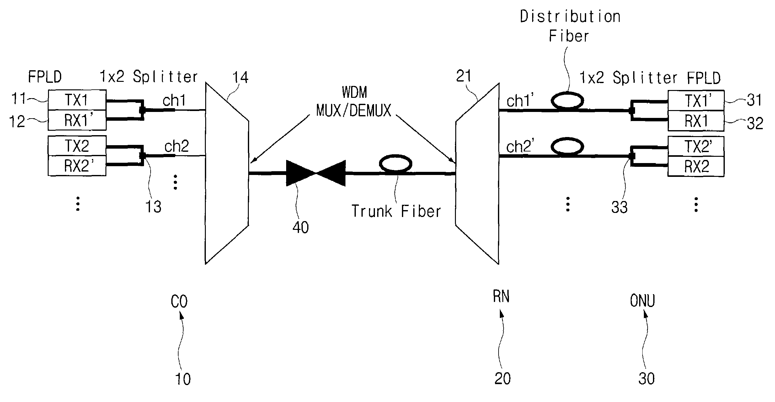
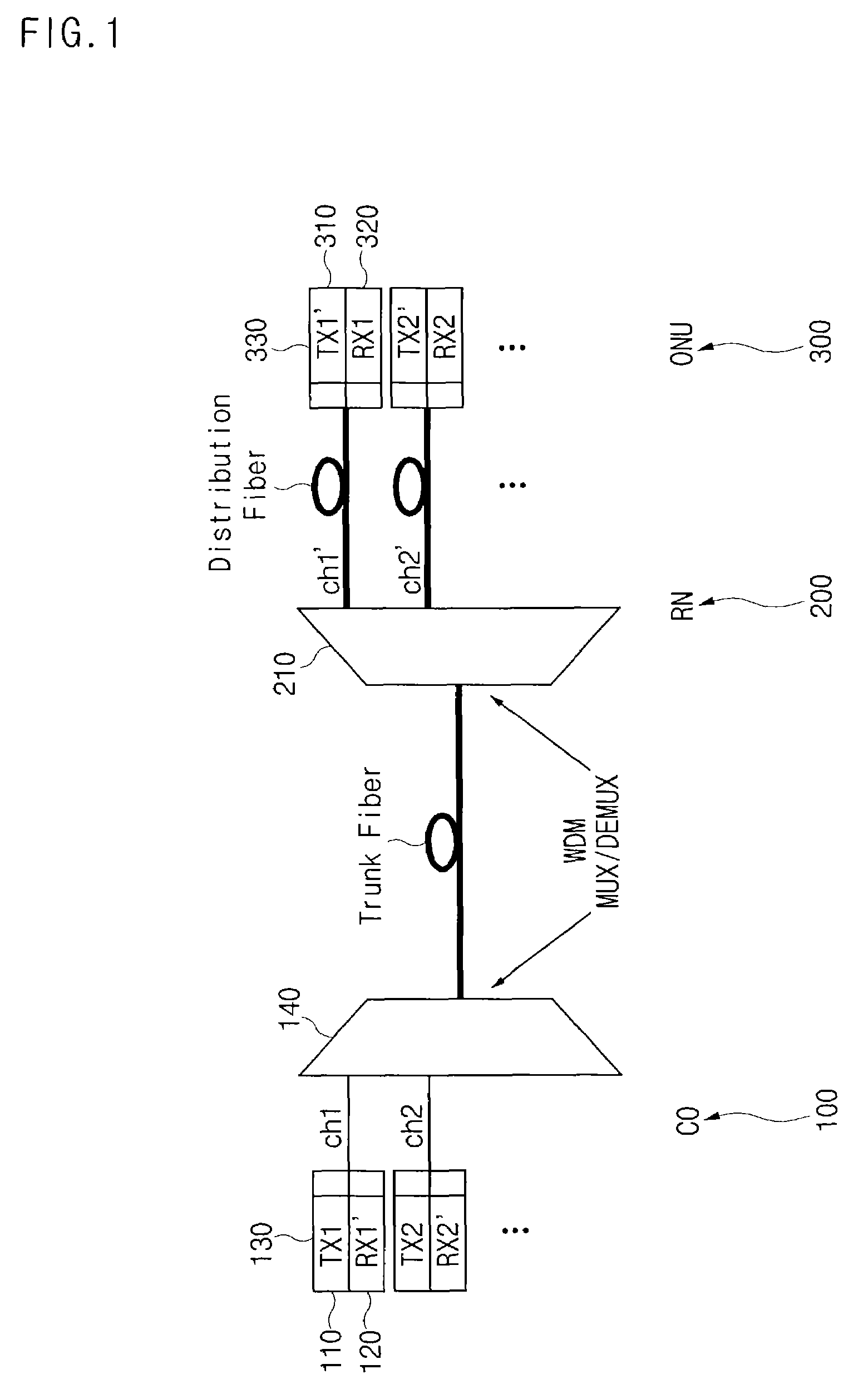
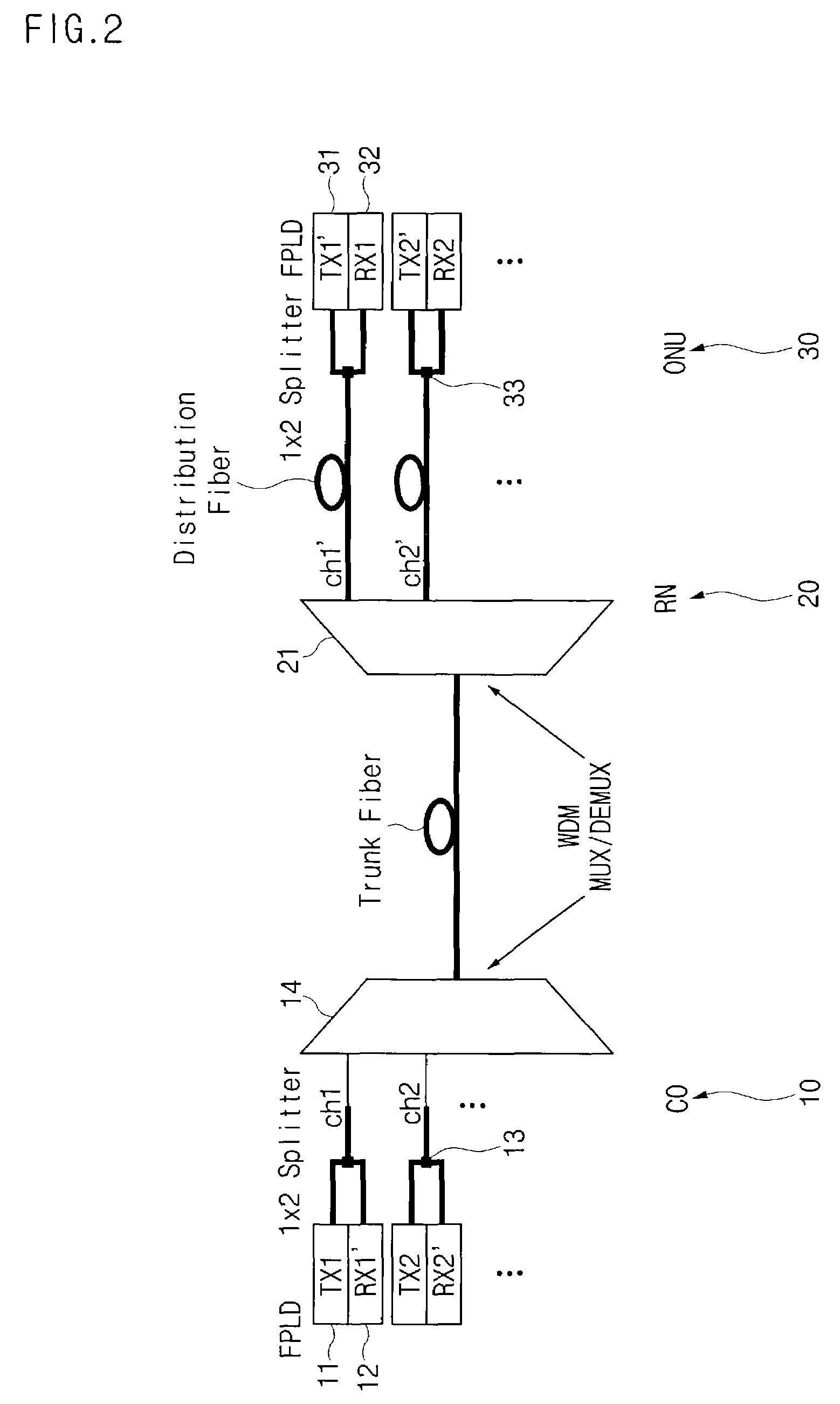
[0042]FIG. 2 is a schematic diagram illustrating the configuration of a WDM PON system according to an embodiment of the present invention. The illustrated system configuration is applicable to the case in which forward and backward signals have the same wavelength. As shown in FIG. 2, the system according to the embodiment of the present invention includes a central office (CO) 10, a remote node (RN) 20, and a plurality of optical network units (ONUs) 30. Each ONU 30 is connected to the central office 10 via optical links.

[0043]When the central office 10 receives optical signals of different particular wavelengths λ1, λ2, . . . λN, it multiplexes the received optical signals, and transmits the multiplexed optical signal to the remote node 20. The remote node 20 demultiplexes the multiplexed optical signal received from ...


PUM


Abstract

Disclosed is a wavelength division multiplexing passive optical network (WDM PON) system in which an optical signal outputted from a central office is injected into a Fabry-Perot laser diode (F-P LD) as the light source of an optical network unit, so that the output wavelength of the optical network unit is injection-locked at the same wavelength as that of the optical signal outputted from the central office, thereby enabling the optical network unit to output an optical signal having the same wavelength as that of the optical signal outputted from the central office. In accordance with this system, it is possible to transmit and receive forward and backward data at the same wavelength by the unit of channels. Since inexpensive F-P LDs are used as respective light sources of the central office and optical network units, it is possible to efficiently and economically implement a WDM PON system.

Description

BACKGROUND OF THE INVENTION[0001]1. Field of the Invention[0002]The present invention relates to a wavelength division multiplexing (WDM) passive optical network system, and more particularly to a WDM passive optical network system in which forward and backward channels have the same wavelength.[0003]2. Description of the Related Art[0004]Recently, demand for broadband multimedia services and high-speed and large-capacity Internet services has abruptly increased. In order to provide, to subscribers, such broadband multimedia services and high-speed and large-capacity Internet services, it is necessary to construct a network architecture based on an optical network. Recently, interest in an optical network directly connected to optical network units (ONUs), using optical fibers, has also increased in order to provide broadband services to subscribers.[0005]In order to construct an effective and economical optical network, active research into passive optical networks (PONS) has also ...

Claims


Application Information

Patent Timeline
IPC IPC(8): H04J14/02H04B10/032H04B10/27H04B10/07H04B10/272H04B10/275H04B10/291H04J14/00H04L12/40H04L12/437
CPCH04J14/0216H04J14/0226H04J14/0227H04J14/028H04J14/0282H04J14/0283H04J14/0293H04J14/0295H04J14/0246H04J14/0247H04J14/025H04J14/0252
Inventor SONG, JAE-WONLEE, JONG-HOONPARK, NO-WOOKSEO, JUN-HYOKJEON, MAN-SHIKJANG, SUCK-WOOBAEK, JANG-KI
Owner CHOI JUN KOOK
Why Eureka
Try Eureka