Modular wine cellar and wine storage system

a wine cellar and module technology, applied in the field of modules, can solve the problems of attracting or possibly detracting buyers' interests, limited in size,

Inactive Publication Date: 2007-08-14
LILKE HARVEY D
View PDF12 Cites 28 Cited by
  • Summary
  • Abstract
  • Description
  • Claims
  • Application Information

AI Technical Summary

Benefits of technology

[0008]It is one object of the present invention to provide an improved wine storage system which makes use of the advantages of the Semi-Conductor or Electro Thermal cooling system.
[0040]The design represented herein is of a modular design, which allows the owner to add additional cooling and / or storage capabilities as he or she may add to their wine collection.
[0046]A unique “quick rack” component (collapsible or knock down wine rack) is also available, which has the same external dimensions as the WCC compartments when opened. Such wine rack component fits firmly and directly into the modular system whereby it will become a conventional bottle storage system. These racks can be easily removed and replaced with WCC units as the owner may decide. These specially designed “quick racks” are made specifically to fit the modular wall rack system. The quick racks are designed so that they collapse / knock down for easy storage and shipping and will open and lock in position for easy insertion into the modular system. Such feature will allow the buyer to utilize the modular system for conventional bottle storage until such time as they may wish to add more WCC units to better protect their growing wine collection. As noted, the modular system can be utilized in various manners, which would not be limited to a singular wall.

Problems solved by technology

The size, design and expense of wine cellars are factors which may attract or possibly detract a buyers interests.
A growing variety of semi-conductor wine cellars are already making entry into the marketplace however all present day models are smaller “free standing” units, which are limited in size.

Method used


Image

  • Modular wine cellar and wine storage system
  • Modular wine cellar and wine storage system
  • Modular wine cellar and wine storage system

Examples


Embodiment Construction

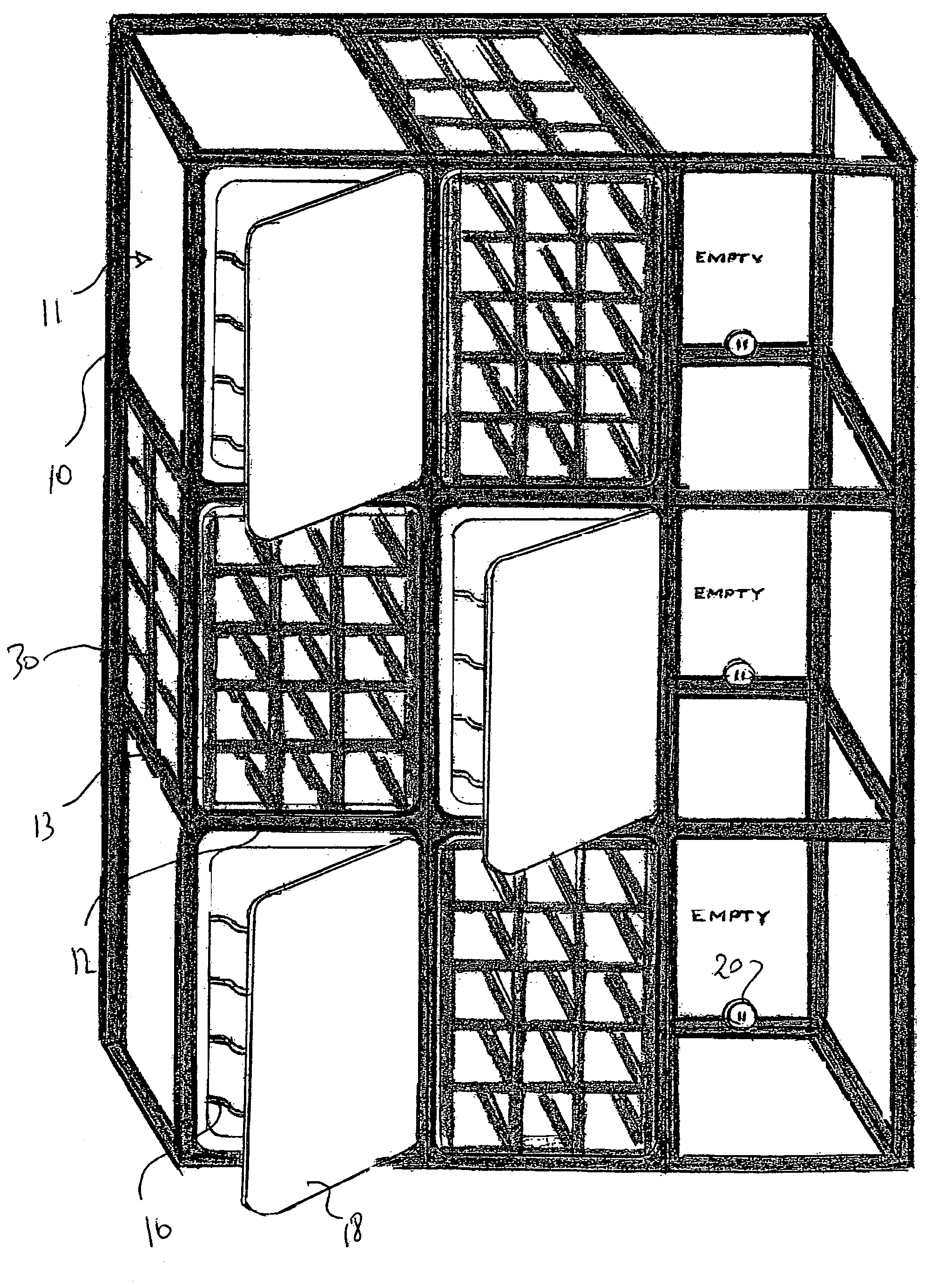
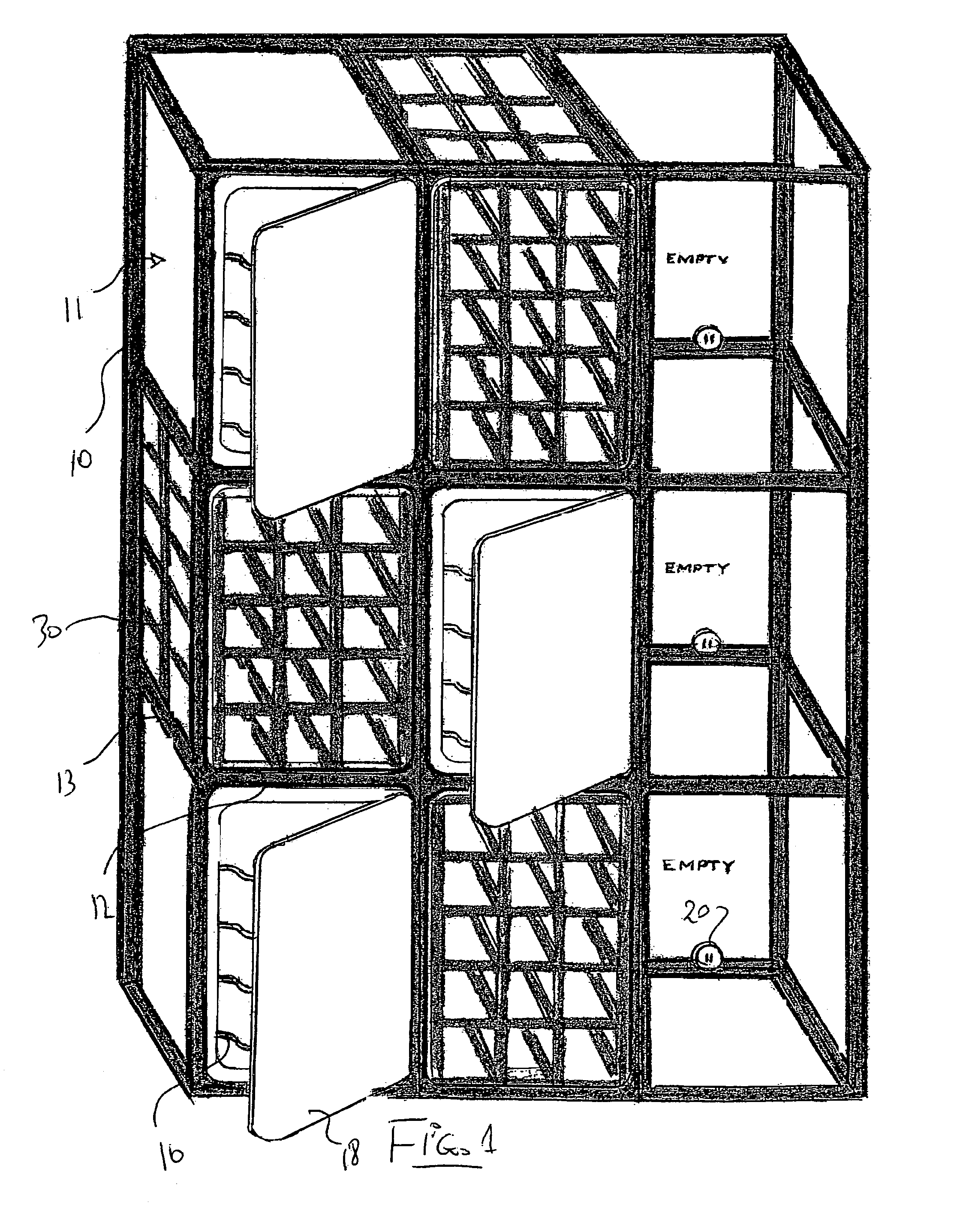
[0055]In FIG. 1 is shown the modular storage system according to the present invention which includes a framework 10 formed of uprights and cross members to form a plurality of compartments 11 arranged in rows and columns. In the arrangement shown there are nine such compartments arranged in three rows and three columns but the frame structure is modular so that it can be increased in height and increased in width to change the number of compartments. The uprights may be continuous and interconnected by horizontal transverse individual cross members 12 extending in the front and rear planes of the frame together with individual cross members 13 extending at right angles to front and rear planes. Many techniques are available for arranging and constructing this modular design to allow interconnection between the uprights of the cross members and allow formation of the structure in a modular form by which the number of compartments can be increased both in the vertical and horizontal ...


PUM


Abstract

A wine storage system is formed by a modular frame defined by upright members and cross members arranged to form a three dimensional array of compartments in rows and columns where the upright members and cross members have interconnections therebetween allowing addition of further members to form frames of different sizes in a modular construction. Each compartment is arranged to receive an independent wine cell having an insulated rectangular housing with a door and a semi-conductor or other based cooling element inside the housing for cooling the wine bottles. A modular electrical supply arrangement provides a single connection for the modular frame and a connector on each compartment for the housing as it slides into the compartment. Some of the housings can be replaced by less expensive knock down or collapsible non-cooling racks for temporary storage. Alternatively the modular frame can be clad by panels and doors and insulated with a central chilling system cooling all the bottles in each of the compartments simultaneously.

Description

[0001]This invention relates to a wine storage system which uses cooling and provides a modularly increasable capacity.BACKGROUND OF THE INVENTION[0002]The most common wine cellars incorporate insulated wood panel walls and doors with built in refrigeration cooling units. This type of design accounts for most all larger wine storage systems and these models can be custom made according to a buyer's discretion and perhaps space limitations. The majority of smaller self-contained wine storage systems are made from metal cabinets similar to refrigerator designs and incorporate glass display doors.[0003]Refrigerated Wine Cellars are made in a variety of standard and custom designs and are available from many sources in the marketplace. There are similarities between most all models being sold and the differences range between design variations, construction features as well as the prices but the basic design and operation principles are the same whereas they use a self contained and cen...

Claims


Application Information

Patent Timeline
Patent Type & Authority Patents(United States)
IPC IPC(8): F25B21/02A47B73/00A47B87/02F25B49/00F25D11/00F25D11/02F25D13/02F25D15/00F25D21/02
CPCA47B73/006A47B87/0284F25D11/00F25D11/02F25D21/02F25B21/02F25D13/02F25D15/00F25D2323/061F25D2331/803F25D2400/16
Inventor LILKE, HARVEY D.
Owner LILKE HARVEY D
Why Eureka
Try Eureka