Clutch for coupling a car door of an elevator car with a landing door of an elevator system

a technology for elevator cars and clutches, which is applied in the direction of door/window fittings, construction fastening devices, and construction. it can solve the problems of difficult to precisely control the motion of the vanes, limiting the lifetime and reliability of the clutch, and affecting the operation efficiency of the second actuator. achieve the effect of high efficiency and high precision

Inactive Publication Date: 2007-08-14
INVENTIO AG
View PDF15 Cites 9 Cited by
  • Summary
  • Abstract
  • Description
  • Claims
  • Application Information

AI Technical Summary

Benefits of technology

[0007]In view of the disadvantages of known clutches, it is the objective of the present invention to provide a clutch which can be independently actuated by means of a separate actuator with high efficiency and with high precision.
[0011]The use of a linear motor in accordance with the present invention has several advantages.
[0012]Linear motors usually provide a high force density since the distance between the motor primary and the motor secondary primary can be kept small. Therefore, optimized linear motors provide a high efficiency. In addition, in the clutch in accordance with the invention, the coupling element can be directly coupled with the linear motor. Thus, the coupling element of the clutch can be directly actuated by means of the linear motor. Consequently, components such as a gear or a screw drive are not necessary for coupling the linear motor with the coupling element. Thus, the coupling element can be actuated with low friction. Therefore, the clutch in accordance with the invention can be efficiently actuated. In addition, the second actuator does not require much space.
[0013]The position and the motion of the movable parts of a linear motor and the force provided by the linear motor can be precisely controlled on the basis of known technologies. Therefore, any movement of the coupling element of the clutch in accordance with the invention can be controlled with high precision. On this basis, the clutch can be operated with high reliability and with low noise.
[0014]If electric power is not supplied, the motor primary and the motor secondary of the linear motor can be easily moved with respect to each other with low friction, for example by hand. This makes it easier to install the motor during the assembly of the clutch and simplifies manual operation of the clutch during power failure.
[0016]In another embodiment of the present invention, the motor secondary is linked to the coupling element by means of a first pivot and the motor primary is rotatable about a second pivot being stationary with respect to the car door. Alternatively, the motor primary may be linked to the coupling element by means of a first pivot and the motor secondary may be rotatable about a second pivot being stationary with respect to the car door. In particular, the coupling element may comprise two vanes that are connected by means of a movable linkage such that the vanes are movable with respect to each other for establishing a mechanical contact of the vanes with the landing door. In each case, the first pivot may be arranged at the linkage or at one of the vanes. On this basis, it is possible to establish a connection between the linear motor and the coupling element, which connection is resistant to wear and, therefore, long-lived.

Problems solved by technology

The sliding contact between the armature and one of the vanes is subjected to wear, thus limiting the lifetime and the reliability of operation of the clutch.
Thus, it is difficult to control the motion of the vanes precisely and to ensure a given accuracy of control over a long time.
In addition, due to the bias of the springs, the operation of the second actuator is not very efficient since the force generated by means of the solenoid must compensate the spring forces.
Due to friction in the gear or in the screw drive, a major part of the energy provided by the DC motor is lost.
Thus, the efficiency of the clutch is reduced.
Furthermore, if electric power is not available for driving the DC motor, it is difficult to operate the gear or the screw drive and, thus, it becomes difficult to actuate any component of the clutch.
This is disadvantageous during the installation of the clutch in the elevator system.
It is difficult or even impossible to exercise this task, depending on the friction in the gear or the screw drive.

Method used


Image

  • Clutch for coupling a car door of an elevator car with a landing door of an elevator system
  • Clutch for coupling a car door of an elevator car with a landing door of an elevator system
  • Clutch for coupling a car door of an elevator car with a landing door of an elevator system

Examples


Embodiment Construction

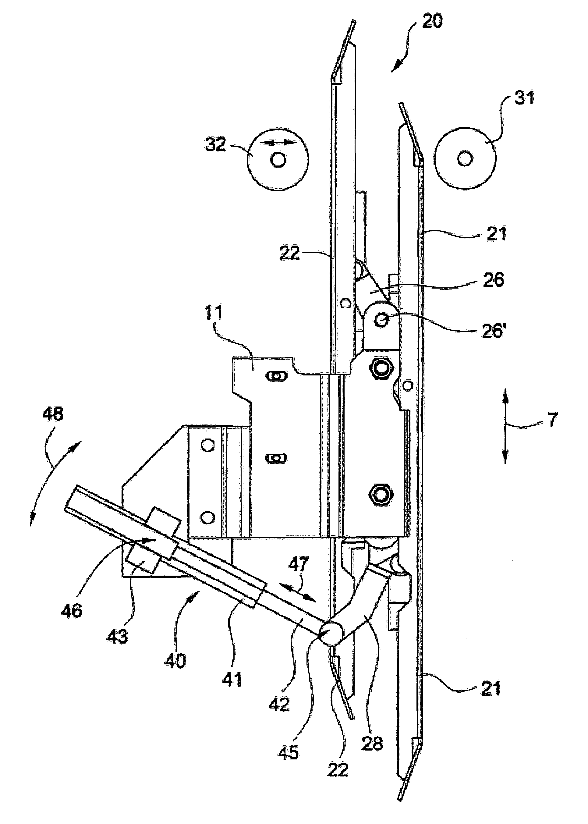
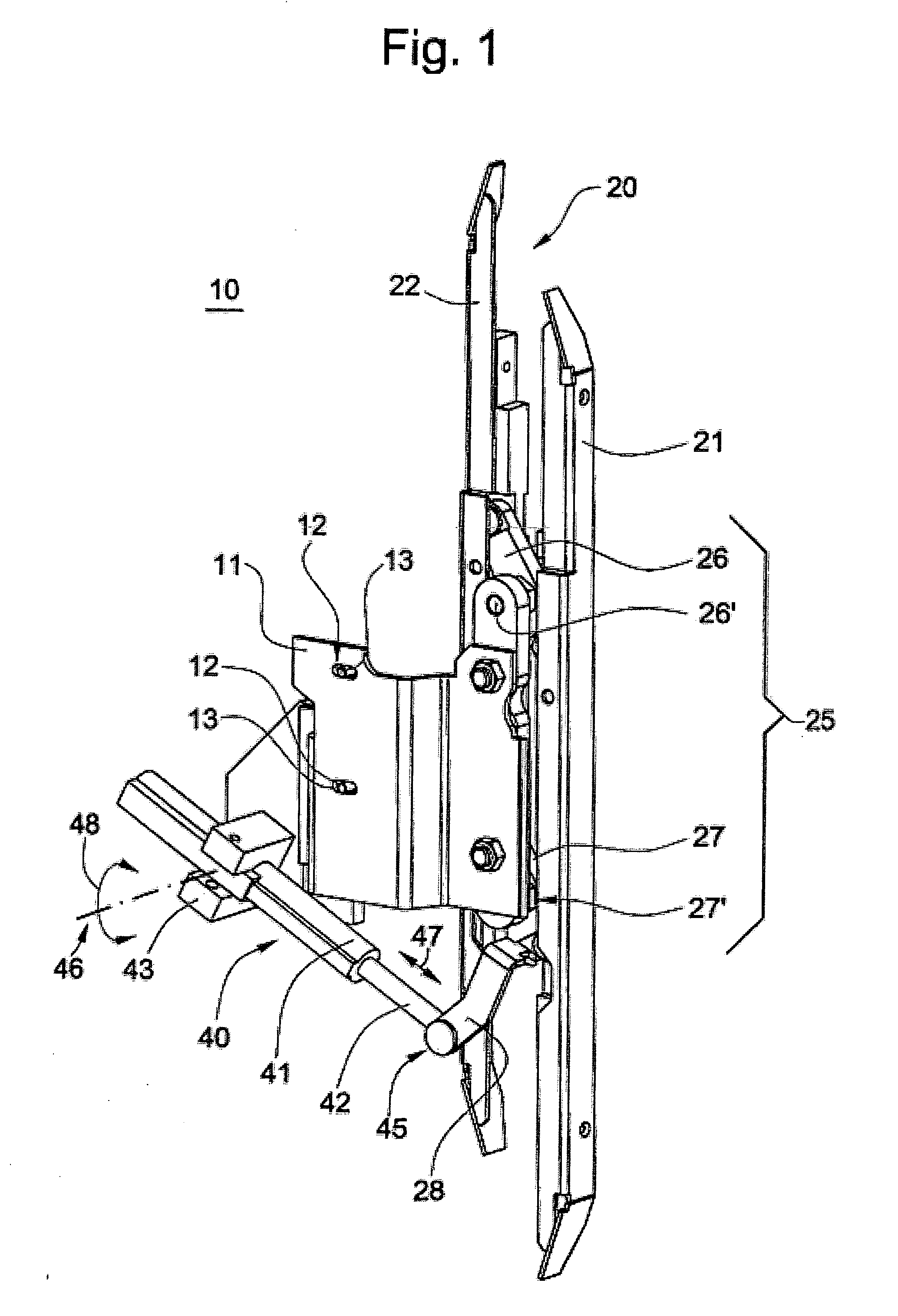
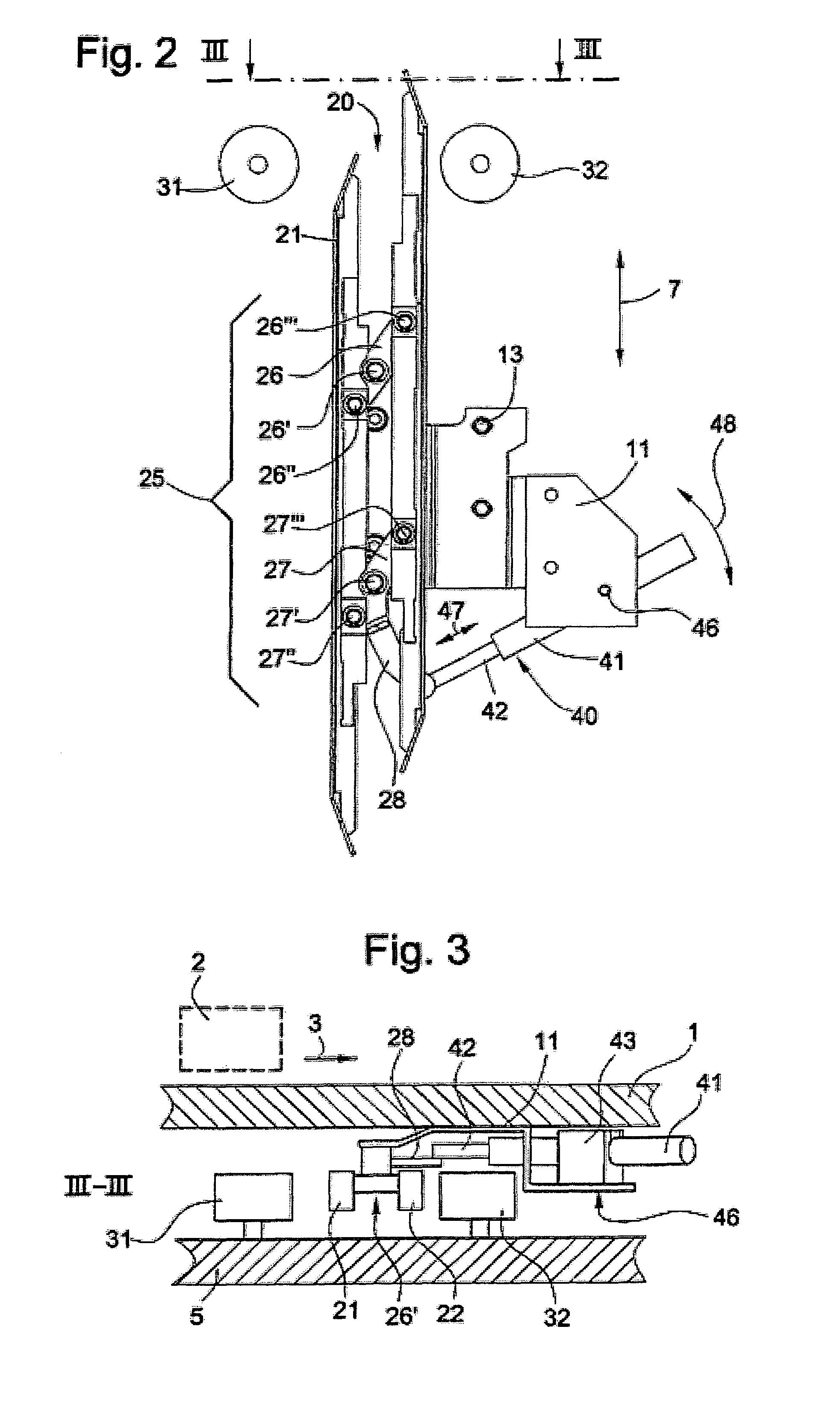
[0023]In FIGS. 1-5, a clutch 10 for coupling a car door of an elevator car with a landing door of an elevator system is shown.

[0024]Referring to FIGS. 1 and 2, the clutch 10 comprises a support 11. At the support 11, all movable parts of the clutch 10 are arranged which are:[0025]a coupling element 20 which consists of two vanes 21, 22 being arranged in parallel and a linkage 25 connecting both vanes 21 and 22,[0026]a linear motor 40 which comprises a motor primary 41 and a motor secondary 42,[0027]a clamp 43 for connecting the motor primary 41 pivotally about a pivot 46 with the support 11 and[0028]a lever 28, one end of which is connected with the motor secondary 42 pivotally about pivot 45 and another end being connected with the linkage 25.

[0029]The linkage 25 comprises a first connecting element 26 and a second connecting element 27. The first connecting element 26 is connected with the support 11 pivotally about a pivot 26′. In addition, the first connecting element 26 is conn...


PUM


Abstract

A clutch couples a car door of an elevator car with a landing door of an elevator system, wherein the car door is movable with respect to the elevator car by a first actuator. The clutch includes at least one coupling element and a second actuator. The coupling element is movable with respect to the car door between a first position and a second position by the second actuator such that the coupling element engages with the landing door when the elevator car is within a landing zone and the coupling element is moved towards the second position, thereby establishing the coupling of the car door with the landing door. The second actuator is a linear motor.

Description

BACKGROUND OF THE INVENTION[0001]The present invention is related to a clutch for coupling a car door of an elevator car with a landing door of an elevator system.[0002]A conventional elevator system comprises two different sets of doors, i.e. car doors and landing doors. In general, each car of the elevator system includes at least one car door. Within each landing zone of the elevator system, at least one landing door is installed. Each landing door is located such that, when the car is stopped within the corresponding landing zone, the landing door is adjacent to a car door so that the interior of the elevator is accessible through the landing door and the car door provided that both doors are open. Under normal conditions, the landing doors are kept closed whenever the car is not present in the related landing zones. Instead of having actuators for each of the landing doors, a particular landing door can be coupled with the car door by means of a clutch that is arranged at the c...

Claims


Application Information

Patent Timeline
Patent Type & Authority Patents(United States)
IPC IPC(8): B66B13/02B66B13/12
CPCB66B13/12
Inventor RENNETAUD, JEAN-MARIEZHOU, TIAN
Owner INVENTIO AG
Why Eureka
Try Eureka