Fluid-filled active damping apparatus

a technology of active damping and damping apparatus, which is applied in the direction of mechanical apparatus, shock absorbers, machine supports, etc., can solve the problems of difficult to consistently achieve the desired drive force and damping effect, the fatigue of the support rubber elastic body relatively early, and the difficulty of adequately achieving the desired vibration damping

Inactive Publication Date: 2007-08-14
SUMITOMO RIKO CO LTD
View PDF28 Cites 18 Cited by
  • Summary
  • Abstract
  • Description
  • Claims
  • Application Information

AI Technical Summary

Benefits of technology

[0014]It is therefore one object of this invention to provide a fluid-filled active damping apparatus of novel construction, whereby the oscillation plate is induced to undergo drive displacement in a stable manner while preventing pressure leakage from the pressure receiving chamber so that the intended vibration damping action is consistently achieved, and whereby oscillation plate dimensions, output member installation location, and the like may be established without an excessive degree of exactitude, thus facilitating manufacture and maintenance.

Problems solved by technology

However, all of these damping apparatus utilize passive vibration damping action.
Thus, if the frequency or other characteristic of vibration to be damped changes, or if a higher level of vibration damping action is required, the known passive damping apparatus are difficult to adequately achieve the desired vibration damping effect.
Thus, there is a tendency for the support rubber elastic body to suffer from its fatigue relatively early, due to the elastic deformation produced repeatedly in the support rubber elastic body during displacement of the oscillation plate.
When the support rubber elastic body has fatigued, created are a change in the support location of the oscillation plate, and accordingly in the relative position of the coil to the output member in the electromagnetic actuator, resulting in the problem of difficulty in consistently achieving the desired drive force and damping effect.
Additionally, since excitation energy is consumed by deformation of the support rubber elastic body, there is the problem of lower drive efficiency of the actuator.
Thus, it is necessary to establish both the through-hole inside diameter dimension and the oscillation plate outside diameter dimension with a very high degree of precision, which presents the problem of difficulty in manufacture and maintenance.
Thus, any error (deviation) in mounting position of the electromagnetic actuator on the mounting assembly will easily result in the center axes of the oscillation plate and the through-hole being misaligned.
Due to this misalignment of their center axes, the oscillation plate will tend to experience interference with the inner peripheral face of the through-hole, even where each of the components has high dimensional accuracy.
Resultant contact of the oscillation plate and the through-hole poses the risk of producing a hammering noise, or of difficulty in achieving the desired oscillation force due to the difficulty of efficiently realizing drive displacement of the oscillation plate.
Thus, an inherent problem is difficulty in consistently achieving drive of the oscillation plate, and difficulty in consistently exhibiting the intended vibration damping effect.

Method used


Image

  • Fluid-filled active damping apparatus
  • Fluid-filled active damping apparatus
  • Fluid-filled active damping apparatus

Examples


Embodiment Construction

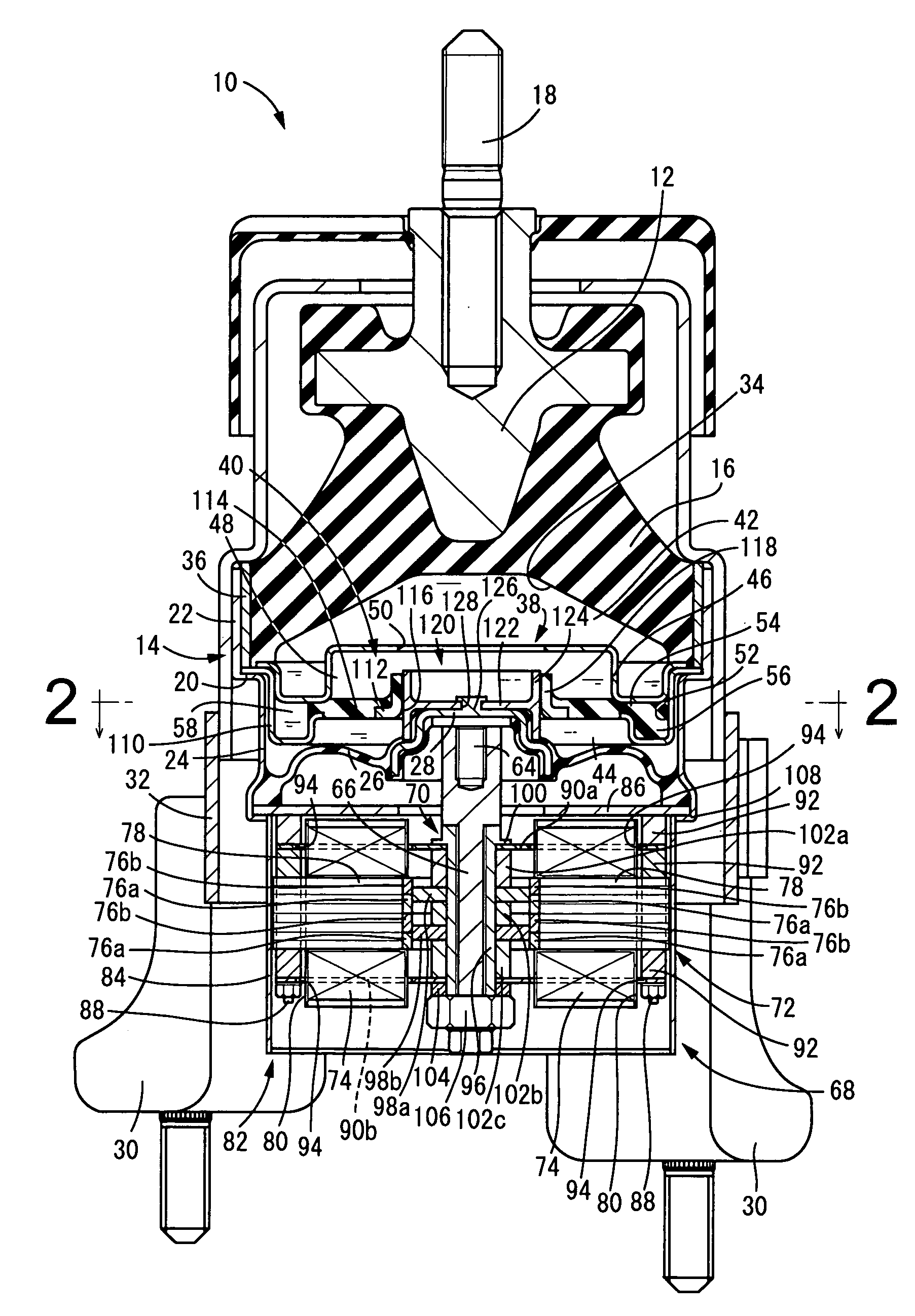
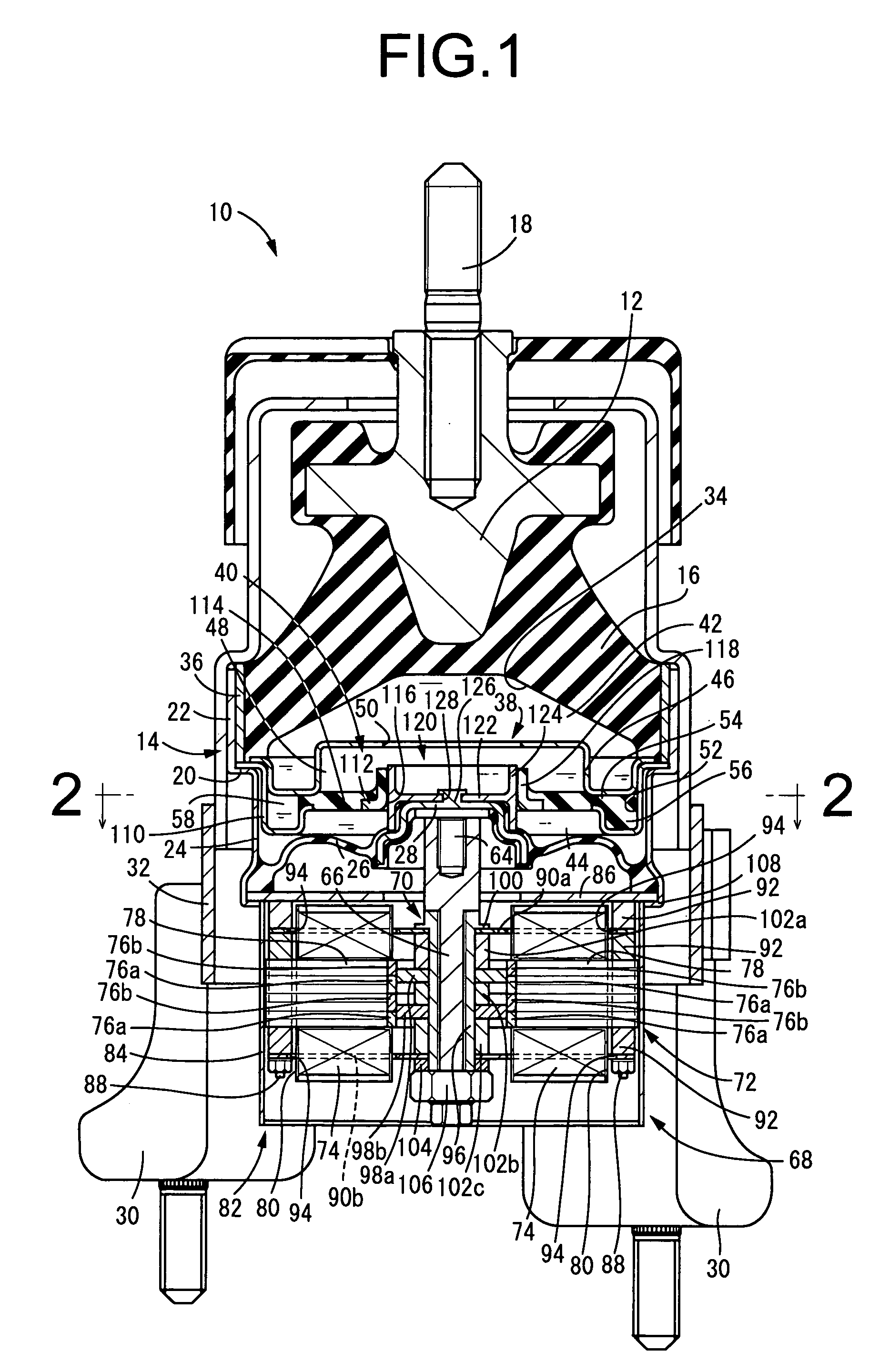
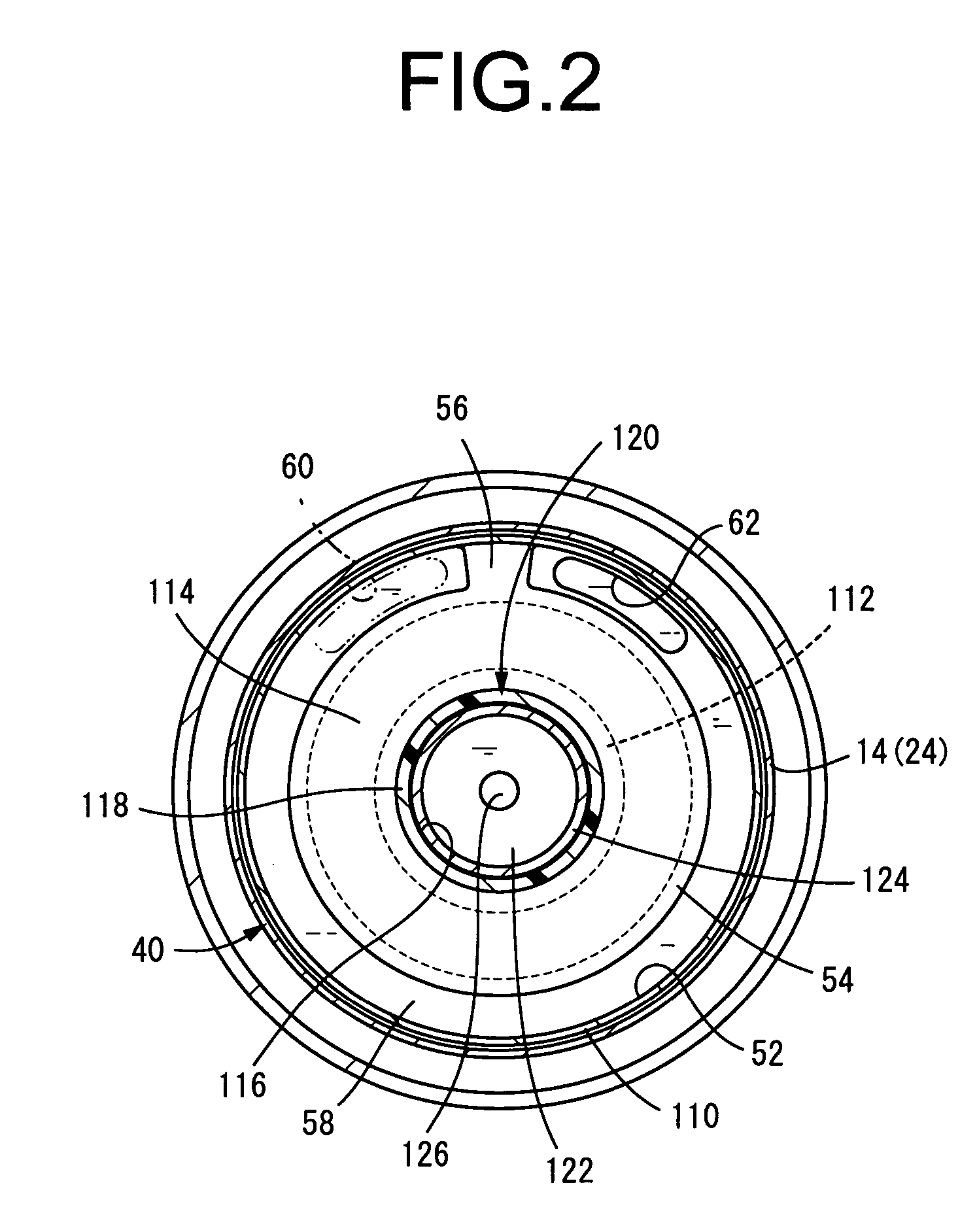
[0043]FIGS. 1 and 2 show an automotive engine mount 10 of construction according to one preferred embodiment of a present invention relating to a fluid-filled active damping apparatus. The engine mount 10 has a construction wherein a metallic first mounting member 12 and a metallic second mounting member 14 are disposed apart from one another by a predetermined distance, and are elastically connected by means of a rubber elastic body 16 interposed therebetween. The first mounting member 12 and the second mounting member 14 are adapted to be fixed respectively to a vehicle body side and to a power unit side, so that the power unit is supported on the body in a vibration-damped manner. During installation on the automobile, the rubber elastic body 16 undergoes elastic deformation due to the weight of the power unit, whereby the first mounting member 12 and the second mounting member 14 undergo relative displacement by a predetermined extent in the proximate direction. The principal vi...


PUM


Abstract

A fluid-filled active damping apparatus having a pressure receiving chamber partially defined by a rubber elastic body connecting a first and second mounting member; an oscillation plate defining a part of the pressure receiving chamber, and supported in a displaceable fashion; an electromagnetic actuator disposed on one side of the oscillation plate remote from the pressure receiving chamber, with its output member connected to the oscillation plate; an equilibrium chamber partially defined by a flexible diaphragm; and an orifice passage connecting the pressure receiving chamber and equilibrium chamber. A rigid annular guide member is disposed about the oscillation plate with a slight gap therebetween, such that these members are mutually displaceable in the axial direction. The guide member is elastically supported by and connected to the second mounting member via an elastic support member.

Description

INCORPORATED BY REFERENCE[0001]The disclosure of Japanese Patent Application No. 2004-176631 filed on Jun. 15, 2004 including the specification, drawings and abstract is incorporated herein by reference in its entirety.BACKGROUND OF THE INVENTION[0002]1. Field of the Invention[0003]The present invention relates to an active damping apparatus of fluid-filled type, adapted to provide dynamic vibration damping action by means of actively controlling pressure fluctuations in a pressure receiving chamber having non-compressible fluid sealed therein, in cycle corresponding to the frequency of vibration to be damped. More particularly, the invention relates to a fluid-filled active damping apparatus of novel construction employing an electromagnetic actuator in order to control pressure fluctuations in the pressure-receiving chamber.[0004]2. Description of the Related Art[0005]A variety of types of damping apparatus known in the art for vibration in a component to be damped, such as a vehi...

Claims


Application Information

Patent Timeline
Patent Type & Authority Patents(United States)
IPC IPC(8): F16F5/00F16F13/00F16F15/00F16F9/00F16M5/00F16F13/26
CPCF16F13/268
Inventor MURAOKA, MUTSUMIMURAMATSU, ATSUSHI
Owner SUMITOMO RIKO CO LTD
Why Eureka
Try Eureka