Use of spray coatings to achieve non-uniform seal clearances in turbomachinery

a technology of turbomachinery and spray coating, which is applied in chemical vapor deposition coating, combination recording, record information storage, etc., can solve the problems of gas or steam leakage, gas or steam entering, or out of gas or steam path, and generally undesirable, and achieve the effect of lowering the efficiency of the gas turbin

Inactive Publication Date: 2007-08-14
GENERAL ELECTRIC CO
View PDF20 Cites 11 Cited by
  • Summary
  • Abstract
  • Description
  • Claims
  • Application Information

AI Technical Summary

Benefits of technology

[0007]A second embodiment of the invention is a method for making a stator component for a turbine assembly. The method comprises providing an annular base component having an inner surface that is substantially circular in axial cross-section and disposing a coating on the inner surface of the base component. The coating has an interfacial surface in contact with the inner surface of the base component and an outer surface opposite the interfacial surface. The coating has a thickness that varies as a function of circumferential position along the inner surface of the base component.

Problems solved by technology

Gas or steam leakage, either out of the gas or steam path or into the gas or steam path, from an area of higher pressure to an area of lower pressure, is generally undesirable.
For example, gas path leakage in the turbine or compressor area of a gas turbine, between the rotor of the turbine or compressor and the circumferentially surrounding turbine or compressor casing, will lower the efficiency of the gas turbine leading to increased fuel costs.
However, overly generous clearances tend to promote undesirable leakages and decreased performance.
Contact between rotating elements and the abradable seal results in trenches worn into the abradable seal, creating a tight clearance between the two.
Effects such as thermal distortion of the casing and vibrations due to rotor dynamics often cause the path of relative rotor motion to become circumferentially non-uniform with respect to the stator.
This non-uniformity of motion can lead to substantial contact in preferential, localized areas of the stator, resulting in undesirable amounts of component wear.
The large clearances allow for more gas or steam to escape, however, which degrades system performance.
In certain cases, parts are machined off-center to provide non-uniform clearances, but this complicates their fabrication and significantly boosts costs.
This greatly complicates turbine assembly because individual parts must be tracked and assembled insitu in their specific circumferential locations.

Method used


Image

  • Use of spray coatings to achieve non-uniform seal clearances in turbomachinery
  • Use of spray coatings to achieve non-uniform seal clearances in turbomachinery

Examples


Embodiment Construction

[0012]In the following description, like reference characters designate like or corresponding parts throughout the several views shown in the figures. It is also understood that terms such as “top,”“bottom,”“outward,”“inward,” and the like are words of convenience and are not to be construed as limiting terms. Moreover, it will be understood that the illustrations are for the purpose of describing a particular exemplary embodiment of the invention and are not intended to limit the invention thereto.

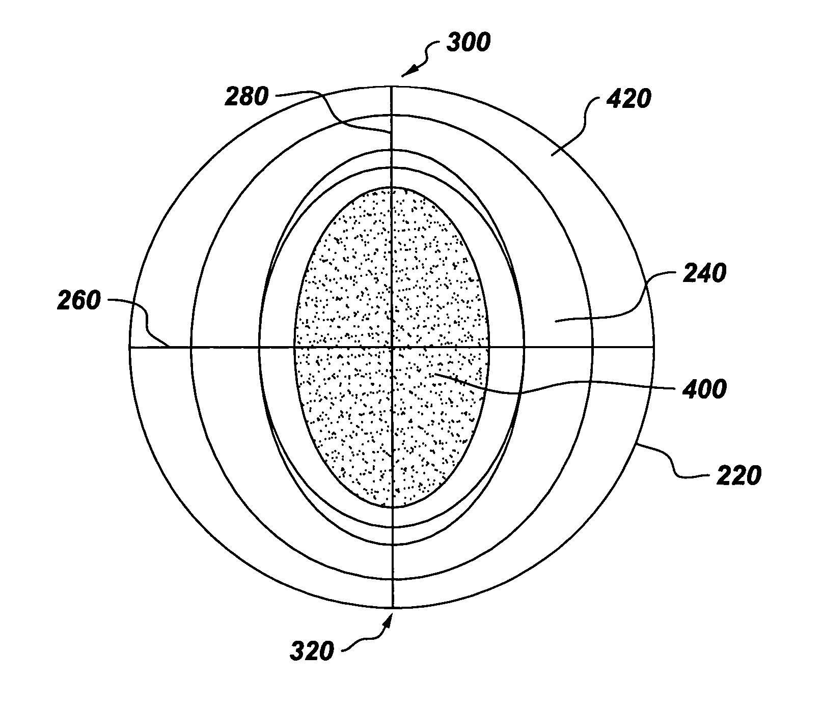
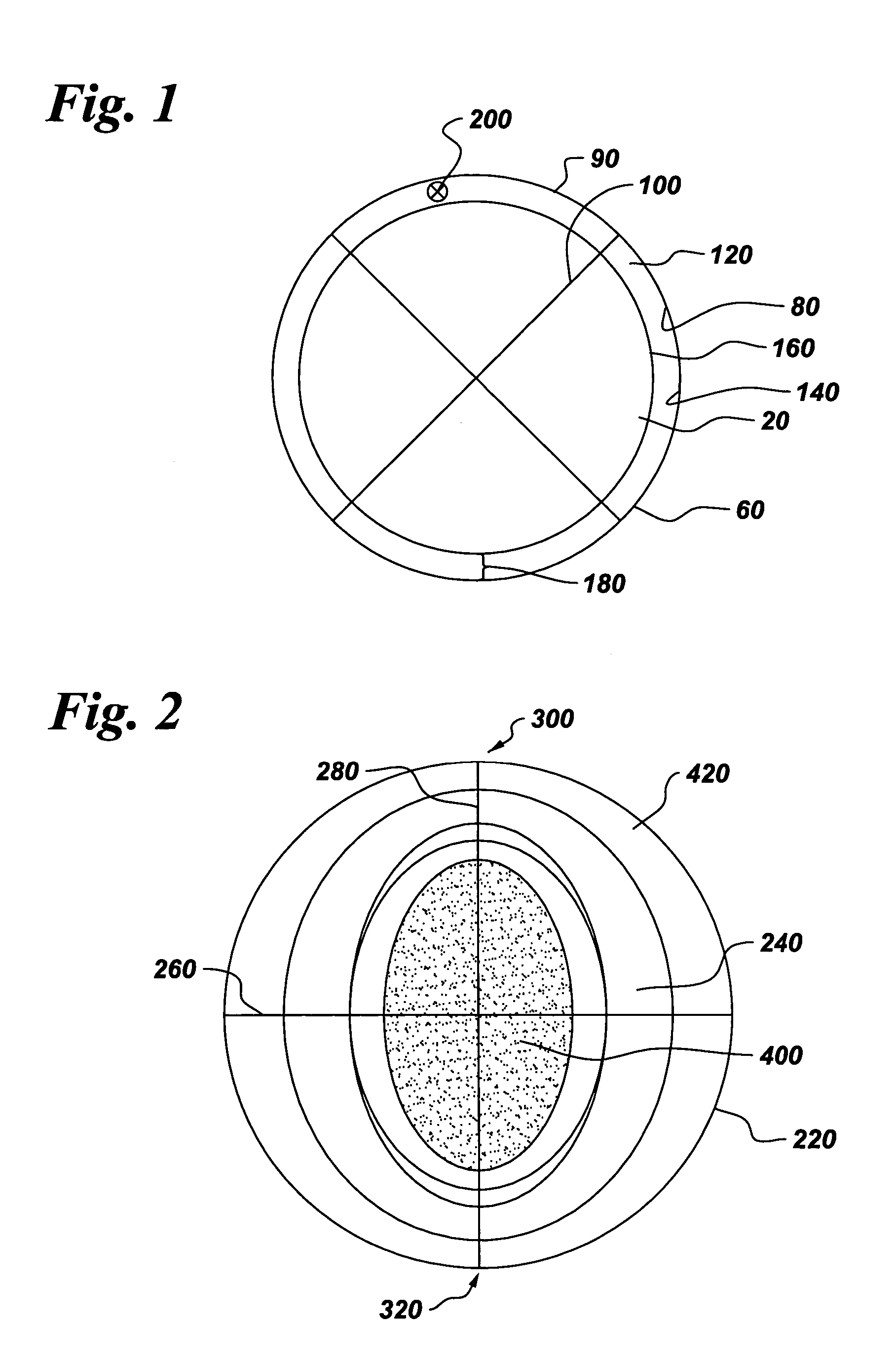
[0013]Referring generally to FIGS. 1 and 2, embodiments of the invention address the needs described above by providing a stator component 20 for a turbine assembly. The stator component 20 comprises an annular base component 60 which, in certain embodiments, comprises at least one of a shroud, a turbine casing and an annular assembly of turbine nozzles. The base component has an inner surface 80 that is substantantially circular 90 in axial cross-section 100; and a coating 120 disposed o...


PUM

PropertyMeasurementUnit
thicknessaaaaaaaaaa
thicknessaaaaaaaaaa
thicknessaaaaaaaaaa

Abstract

The invention provides spray coatings to achieve circumferentially non-uniform seal clearances in turbomachines. In steam and gas turbines it is desirable to assemble the machines with elliptical seal clearances to compensate for expected casing distortion, rotordynamics or phenomena that cause circumferentially non-uniform rotor-stator rubs. The claimed invention allows the casing hardware to be fabricated round, and a spray coating is applied to the radially inner surface such that the coating thickness varies circumferentially, providing the desired non-uniform rotor-stator clearance during assembly.

Description

BACKGROUND OF THE INVENTION[0001]The invention relates to seal clearances in rotary machines. More particularly, the invention relates to a method to modify the stationary casing in a manner to compensate for circumferentially non-uniform rotor movements.[0002]Rotary machines include, but are not limited to, gas turbines and steam turbines. The moving part of the turbine is called a rotor and the fixed, non-moving part i. e. housings, casings etc. a stator. Usually, the rotor rotates within a stator assembly at very high speeds, powering a generator which in turn produces electricity or power. A steam turbine has a steam path that typically includes, in serial-flow relationship, a steam inlet, a turbine, and a steam outlet. A gas turbine has a gas path, which typically includes, in serial-flow relationship, an air intake (or inlet), a compressor, a combustor, a turbine, and a gas outlet (or exhaust nozzle). Gas or steam leakage, either out of the gas or steam path or into the gas or...

Claims


Application Information

Patent Timeline
Patent Type & Authority Patents(United States)
IPC IPC(8): F01D11/14B32B15/04B32B3/02B32B3/26B32B7/02F01D11/08F02C7/00F02C7/28F04D29/08
CPCF01D11/08F05D2230/30F05D2240/55F05D2230/90Y10T428/12944Y10T428/12389Y10T428/12201Y10T428/26Y10T428/2495
Inventor TURNQUIST, NORMAN ARNOLDKOWALCZYK, MARK WILLIAMGHASRIPOOR, FARSHAD
Owner GENERAL ELECTRIC CO
Why Eureka
Try Eureka