LED power control methods and apparatus

a technology of power control and control method, applied in the direction of electric variable regulation, process and machine control, instruments, etc., can solve the problems of feedback control loop, unpredictable amount of energy, and potential inductance energy build-up, so as to improve overall power efficiency, and reduce the effect of functional redundancy of components

Active Publication Date: 2007-08-14
SIGNIFY NORTH AMERICA CORP
View PDF124 Cites 509 Cited by
  • Summary
  • Abstract
  • Description
  • Claims
  • Application Information

AI Technical Summary

Benefits of technology

[0054]Various embodiments of the present disclosure are directed generally to methods and apparatus for providing and controlling power to at least some types of loads, wherein overall power efficiency typically is improved and functional redundancy of components is significantly reduced as compared to conventional arrangements. In different aspects, implementations of methods and apparatus according to various embodiments of the disclosure generally involve significantly streamlined circuits having ewer components, higher overall power efficiencies, and smaller space requirements.
[0055]In some embodiments, a controlled predetermined power is provided to a load without requiring any feedback information from the load (i.e., without monitoring load voltage and / or current). Furthermore, in one aspect of these embodiments, no regulation of load voltage and / or load current is required. In another aspect of such embodiments in which feedback is not required, isolation components typically employed between a DC output voltage of a DC-DC converter (e.g., the load supply voltage) and a source of power derived from an AC line voltage (e.g., a high DC voltage input to the DC-DC converter) in some cases may be eliminated, thereby reducing the number of required circuit components. In yet another aspect, eliminating the need for a feedback loop generally increases circuit speed and avoids potentially challenging issues relating to feedback circuit stability.
[0056]Based on the foregoing concepts, one embodiment of the present disclosure is directed to a “feed-forward” driver for an LED-based light source. Such a feed-forward driver (also referred to herein as a “power control apparatus”) utilizes information known in advance regarding a desired power to be provided to the light source, and combines the functionality of a DC-DC converter and a light source controller to control the intensity of radiation generated by the light source based on modulating the average power delivered to the light source in a given time period, without monitoring or regulating the voltage or current provided to the light source. In one aspect of this embodiment, the feed-forward driver is configured to store energy to, and release energy from, one or more energy transfer elements using a “discontinuous mode” switching operation. This type of switching operation facilitates the transfer of a predictable quantum of energy per switching cycle, and hence a predictable controlled power delivery to the light source. The discontinuous mode switching operation employed in this embodiment may be similarly used in various feed-forward implementations for providing power to loads other than LED-based light sources (e.g., motors, actuators, relays, heating elements, etc.)
[0057]In another embodiment, the concept of “feeding-forward” known information about desired load conditions is utilized to facilitate power factor correction. For example, in one embodiment, a modified power factor correction apparatus according to the present disclosure is based on a DC-DC converter switching architecture (e.g., a boost converter), wherein control of the apparatus' switching operation is based on a predetermined desired load power and, more particularly, a total anticipated power draw from an AC power source. By knowing in advance the desired load power and determining the total anticipated power draw, the overall control loop response of the power factor correction apparatus may be significantly improved, particularly in situations in which the load power traverses a wide range in a short time period (e.g., load full off to load full on, or vice versa). Hence, a more stable power factor correction may be realized, in which smaller circuit components may be employed based on more predictable expectations for signal values, thereby reducing the cost and / or size of the implemented circuits.
[0058]In another embodiment, a power factor correction apparatus as described immediately above may be used in combination with one or more feed-forward drivers to efficiently provide power from an AC power source to one or more of a variety of loads, including LED-based light sources.
[0080]Another embodiment is directed to a power factor correction method, comprising an act of controlling a current drawn from an AC power source based at least on a predetermined desired power to be provided to a load from the AC power source, so as to improve a power factor associated with the provision of actual power to the load.

Problems solved by technology

One of the issues addressed by current-mode regulators is that of potentially unpredictable energy build-up in the inductor during successive switching cycles.
This situation generally results in a somewhat unpredictable amount of energy being transferred via the inductor (or other energy transfer element) in any given switching cycle.
The feedback control loop in the circuits discussed above, however, generally has a limited response time, and there may be some changes in input conditions (e.g., Vin) and / or output power requirements of the DC-DC converter that could compromise the stability of the feedback control loop.
Also, the unregulated DC input voltage to the converter may be approximately 160 Volts DC (based on a rectified 120 Vrms line voltage) or higher (up to approximately 400 Volts if power factor correction is employed, as discussed below in connection with FIGS. 9A and 9B), which is potentially quite dangerous.
This condition may have some generally undesirable effects when DC-DC converters draw power from an AC power source (e.g., as in the arrangements of FIGS. 8 and 9).
The switching nature of the DC-DC converter and resulting pulsed current draw (i.e., significantly non-sinusoidal current draw), however, causes these apparatus to have less than unity power factor, and thus less than optimum power efficiency (notwithstanding their improved efficiency over conventional linear supplies).
Additionally, if the DC-DC converter were to draw current from the AC line voltage with only intervening rectification and filtering, the pulsed non-sinusoidal current drawn by the DC-DC converter would place unusual stresses and introduce generally undesirable noise and harmonics on the AC line voltage (which may adversely affect the operation of other devices drawing power from the AC line voltage).
In particular, such power factor correction apparatus generally operate to “smooth out” the pulsed current drawn by a DC-DC converter, thereby lowering its RMS value, reducing undesirable harmonics, improving the power factor, and reducing the chances of an AC mains circuit breaker tripping due to peak currents.
Due to the relatively slow response time, though, this action may in turn cause an over-voltage condition for Vin, particularly if the sudden / excessive demand from the load no longer exists by the time an adjustment to Vin is made.
The apparatus then tries to compensate for the over-voltage condition, again subject to the slow response time of the voltage feedback loop 524, leading to some degree of potential instability.

Method used


Image

  • LED power control methods and apparatus
  • LED power control methods and apparatus
  • LED power control methods and apparatus

Examples


Embodiment Construction

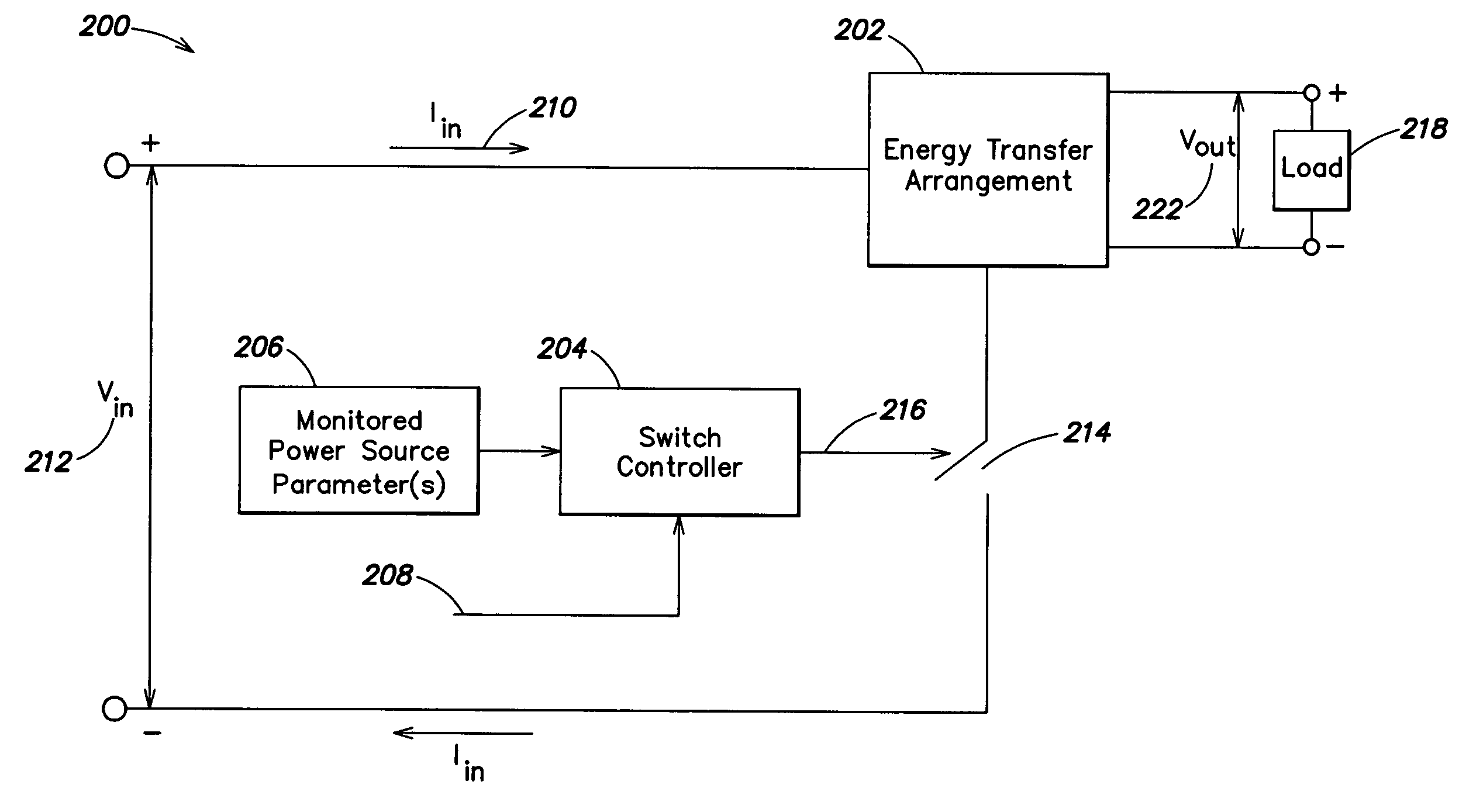
[0127]Applicants have recognized and appreciated that for some power supply applications and some types of loads, commercially available conventional switching power supplies based on DC-DC converters may not be best configured to facilitate a flexible and / or efficient provision of power to a load. For example, although the power conversion efficiency of many conventional switching supplies is on the order of approximately 80% (from A.C. line voltage to a regulated DC voltage output), particular configurations and / or control requirements of different loads may significantly reduce the overall power conversion efficiency of a system that includes a DC-DC converter and a load, wherein the load itself may include various control circuitry.

[0128]Additionally, Applicants have recognized and appreciated that for some applications and for some types of loads, the functions of providing appropriate power to the load and controlling some functionality associated with the load may be signific...


PUM


Abstract

Methods and apparatus for providing and controlling power to loads including one or more LEDs. In one example, a controlled predetermined power is provided to a load without requiring any feedback information from the load (i.e., without monitoring a load voltage and / or load current). In another example, a “feed-forward” power driver for an LED-based light source combines the functionality of a DC-DC converter and a light source controller, and is configured to control the intensity of light generated by the light source based on modulating the average power delivered to the light source in a given time period, without monitoring and / or regulating the voltage or current provided to the light source. In various examples, significantly streamlined circuits having fewer components, higher overall power efficiencies, and smaller space requirements are realized. Based on various power driver configurations, lighting apparatus incorporating one or more power drivers for one or more LED-based loads may be implemented, and multiple such lighting apparatus may be coupled together to form a lighting network in which operating power is efficiently provided throughout the network.

Description

CROSS-REFERENCE TO RELATED APPLICATIONS[0001]The present application claims the benefit, under 35 U.S.C. §119(e), of U.S. Provisional Application Ser. No. 60 / 553,318, filed Mar. 15, 2004, entitled “Power Control Methods and Apparatus,” which application is hereby incorporated herein by reference.FIELD OF THE INVENTION[0002]The present disclosure relates generally to controlling power delivered to a load. In some examples, a controlled predetermined power is provided to a load without requiring any feedback from the load (e.g., without monitoring load voltage and current) and / or regulation of load voltage or load current.BACKGROUND[0003]A DC-DC converter is a well-known electrical device that accepts a DC input voltage and provides a DC output voltage. DC-DC converters generally are configured to provide a regulated DC output voltage to a load based on an unregulated DC input voltage which in some cases is different from the regulated output voltage. For example, in many automotive a...

Claims


Application Information

Patent Timeline
Patent Type & Authority Patents(United States)
IPC IPC(8): G05F1/00H02M1/42H02M3/155H02M3/156H02M3/157H02M3/335H05B37/02H05B41/24H05B44/00
CPCF21S48/325F21S48/328H02M1/4225H02M1/425H02M3/155H02M3/156H02M3/157H02M3/33561H05B33/0803H05B33/0815H05B33/0818H05B33/0842H05B33/0848H05B33/0866H02M2001/0012H02M2001/0019H02M2001/008H02M2001/4291Y02B70/126H05B45/14H05B45/3725H05B45/355Y02B70/10H05B45/305H05B45/375H05B45/38H05B45/385H05B45/10H02M1/0019H02M1/0012H02M1/008H02M1/4291H02M3/335H05B41/24H05B45/24
Inventor LYS, IHOR A.
Owner SIGNIFY NORTH AMERICA CORP
Why Eureka
Try Eureka