Supercharge Your Innovation With Domain-Expert AI Agents!

Particle detecting system and method of detecting particles using the same

a particle detection and particle technology, applied in the field of particle detection systems, can solve the problems of degrading the photo-lithography process, affecting the proper formation of circuit patterns on the substrate, and affecting the exposure process

Inactive Publication Date: 2007-08-14
SAMSUNG ELECTRONICS CO LTD
View PDF22 Cites 2 Cited by
  • Summary
  • Abstract
  • Description
  • Claims
  • Application Information

AI Technical Summary

Benefits of technology

Enables accurate detection of particles regardless of pellicle thickness or type, improving the reliability of the photo-lithography process by adapting the light angle dynamically.

Problems solved by technology

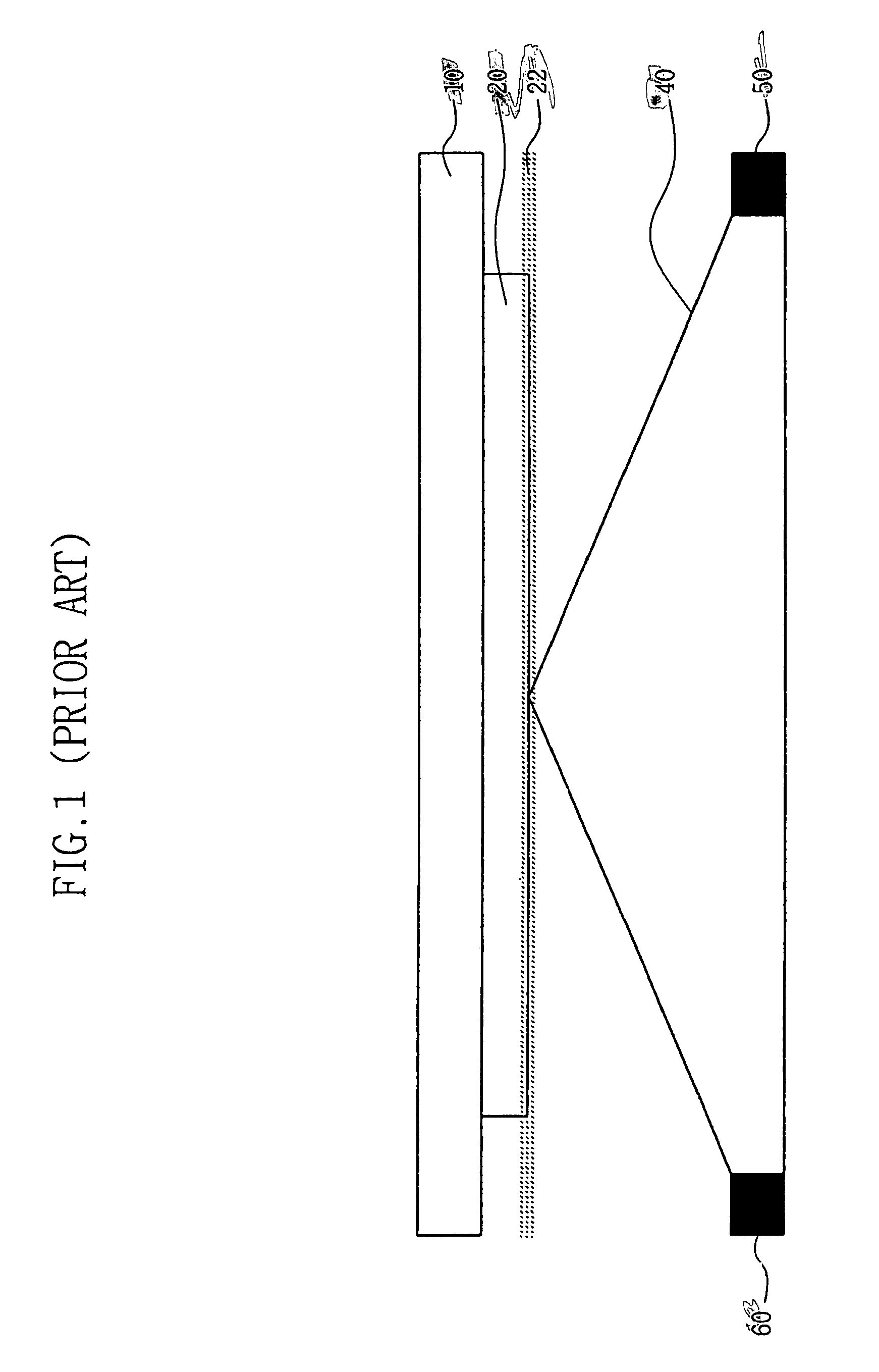
However if particles, such as dust, contaminate the surface of the reticle, the photo-lithography process can be degraded, impairing the proper formation of circuit patterns on a substrate.
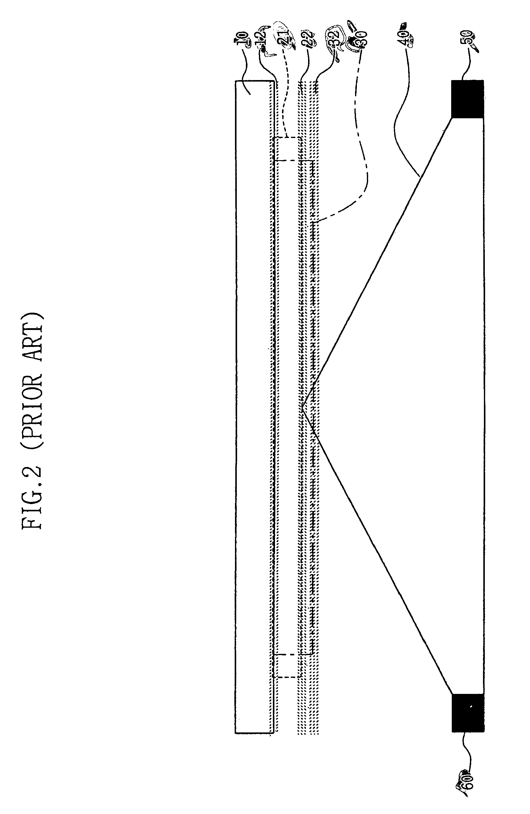
However, when a pellicle is employed, particles can also adhere to the pellicle, thereby degrading the exposure process and impairing the proper formation of circuit patterning on a substrate.
However, it is impossible for the conventional particle detector to adjust the incident angle of light.

Method used


Image

  • Particle detecting system and method of detecting particles using the same
  • Particle detecting system and method of detecting particles using the same
  • Particle detecting system and method of detecting particles using the same

Examples


Embodiment Construction

[0028]The present invention will now be described hereinafter with reference to the attached drawings, in which preferred embodiments of the present invention are shown. The present invention may, however, be embodied in different forms and should not be construed as limited to the embodiments set forth herein. Rather, these embodiments are provided as teaching examples of the present invention. Like numbers refer to like elements. The present invention embodies a particle detector using a liquid microlens. FIG. 3 shows a droplet 70 disposed on a dielectric insulating layer 80. Droplet 70 is preferably a conducting liquid such as water. An electrode 90 is positioned below dielectric insulating layer 80. When a voltage is applied between droplet 70 and electrode 90, droplet 70 spreads evenly across dielectric insulating layer 80.

[0029]This is referred to as an electrowetting phenomenon or electrocapillarity By the electrowetting phenomenon, contact angle a of droplet 70 is a function...


PUM

PropertyMeasurementUnit
incident angleaaaaaaaaaa
refraction angleaaaaaaaaaa
photosensitiveaaaaaaaaaa

Abstract

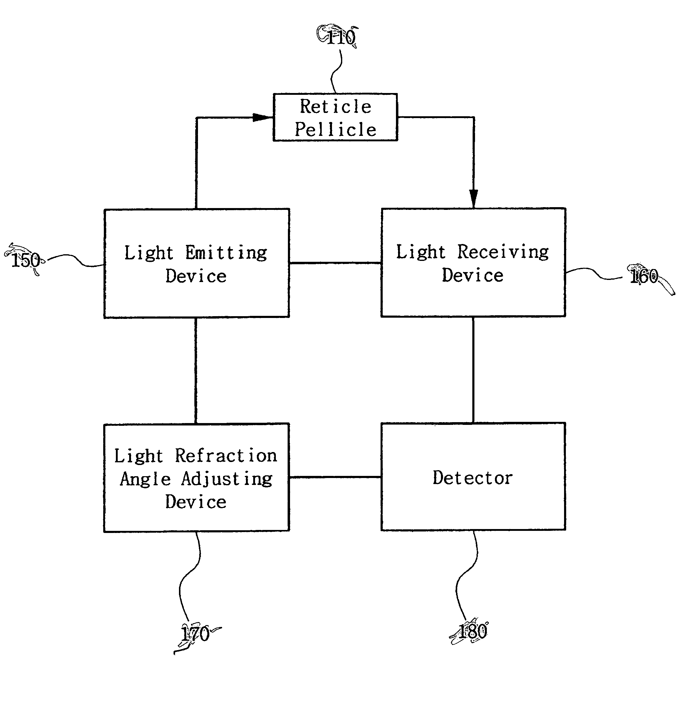
There is provided a particle detector system and to detect particles on target including reticle and pellicle. The system includes a light transmitting device adapted to transmit light beam to a target through an electrowetting microlens, a light receiving device adapted to receive the transmitted light beam reflected by a surface of the target, a light refraction angle adjusting controller adapted to apply a voltage to the electrowetting microlens in order to adjust an incident angle of the light irradiated, and a detector adapted to analyze the light received by the light receiving device to determine whether there are particles on a surface of the target.

Description

BACKGROUND OF THE INVENTION[0001]1. Technical Field[0002]The present invention generally relates to a particle detector and a method of using the same. More particularly, the present invention generally relates to a system used to detect particles by using an electrowetting microlens and a method of detecting particles using the same.[0003]A claim of priority is made to Korean Patent Application No. 2004-0038060, filed May 28, 2004, the disclosure of which is hereby incorporated herein by reference in its entirety.[0004]2. Discussion of Related Art[0005]Developments in semiconductor devices are increasing almost on a daily basis. The development of ultra highly integrated semiconductor devices has advanced the electronic communication industry and the multimedia field. The development of the semiconductor devices is an aggregate of circuit design technology, equipment technology, and process technology.[0006]Manufacturing processes for a semiconductor device consist of photo-lithogr...

Claims


Application Information

Patent Timeline
Patent Type & Authority Patents(United States)
IPC IPC(8): G01N21/00H01L21/027G01N21/88G01N21/94G01N21/95
CPCG01N21/94G01N21/9501G03F1/62G03F1/84H01L21/67288H01L22/12
Inventor KIM, SANG-HUN
Owner SAMSUNG ELECTRONICS CO LTD
Features
  • R&D
  • Intellectual Property
  • Life Sciences
  • Materials
  • Tech Scout
  • Unparalleled Data Quality
  • Higher Quality Content
  • 60% Fewer Hallucinations
Learn More