Method of automatic shape-based routing of interconnects in spines for integrated circuit design

a technology of integrated circuit design and spine, which is applied in the direction of electric digital data processing, instruments, special data processing applications, etc., can solve the problems of insufficient linear interconnect generation of traditional routers, and insufficient routing of traditional routers. achieve the effect of fast execution times and facilitate the improvement of the routing quality of interconnects

Active Publication Date: 2007-08-14
PULSIC
View PDF79 Cites 60 Cited by
  • Summary
  • Abstract
  • Description
  • Claims
  • Application Information

AI Technical Summary

Benefits of technology

[0011]The present invention provides a technique for routing interconnects of integrated circuits, and is broadly applicable to many types of integrated circuit including custom, semicustom, and high-performance integrated circuits. In an embodiment, the technique of the present invention is embodied in a computer software program that is to be executed by a computer system. In particular, the technique facilitates improved routing quality of interconnects and has fast execution times. The technique is applicable to small circuits having relatively few components and is especially suited for integrated circuits having hundreds, thousands, or millions of components.

Problems solved by technology

Such designs are much too large for an integrated circuit designer to manage effectively manually.
To route interconnect manually between the inputs and outputs, it would take an integrated circuit designer an inordinate amount of time.
In particular, traditional routers do not necessarily generate optimal linear interconnects.
For example, a traditional router often produces interconnect with many jogs and bends, which do not facilitate a fast signal path.
However, manual rerouting is time consuming, especially for large designs, may introduce design rule violations, and the results of manual rerouting may not be optimal.

Method used


Image

  • Method of automatic shape-based routing of interconnects in spines for integrated circuit design
  • Method of automatic shape-based routing of interconnects in spines for integrated circuit design
  • Method of automatic shape-based routing of interconnects in spines for integrated circuit design

Examples


Embodiment Construction

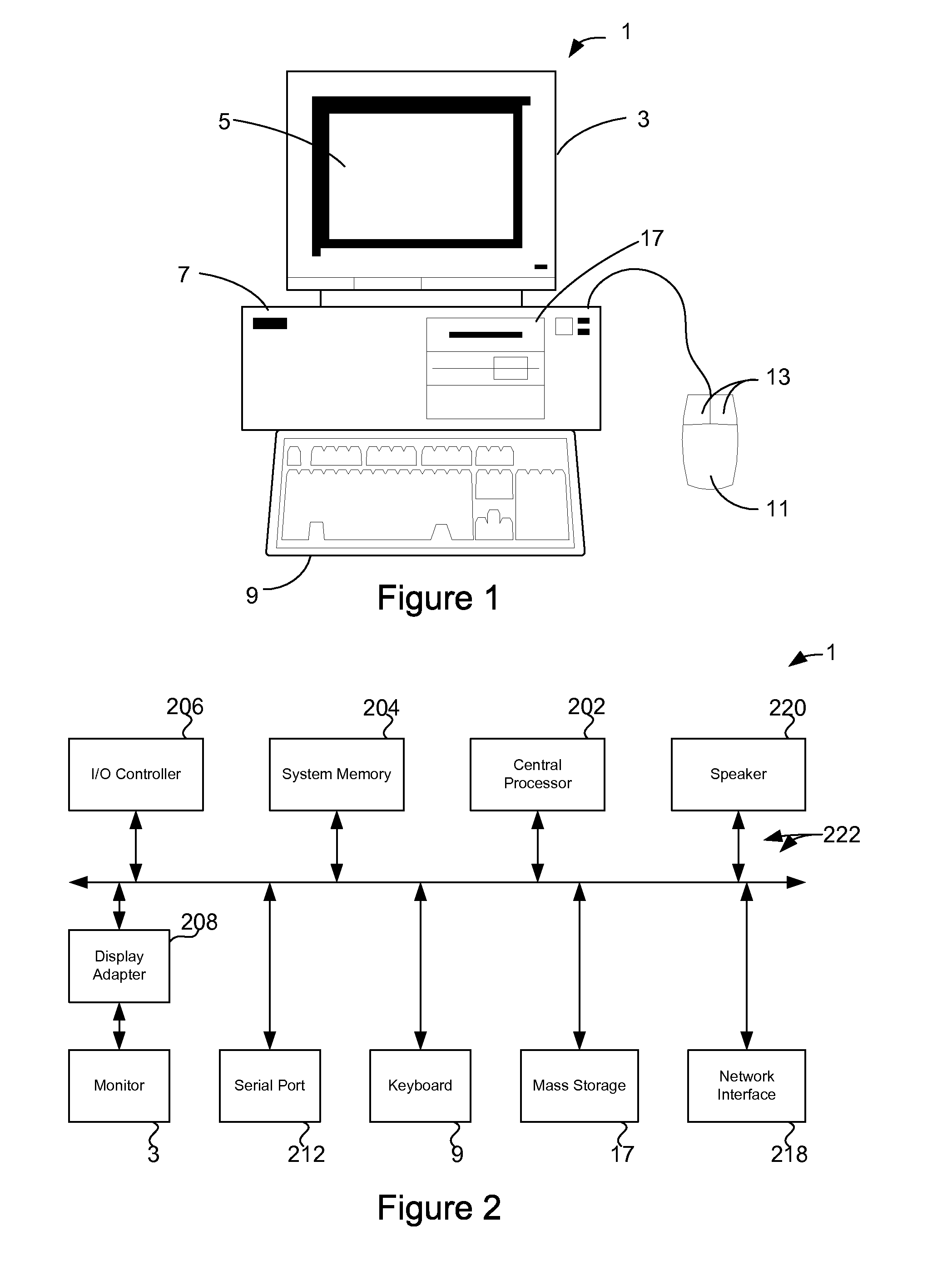
[0034]FIG. 1 shows an electronic design automation (EDA) system of the present invention for designing an electronic circuit or integrated circuit, including automatic shape-based routing of interconnect in spines for integrated circuit design. In an embodiment, the invention is software that executes on a computer workstation system, such as shown in FIG. 1. FIG. 1 shows a computer system 1 that includes a monitor 3, screen 5, cabinet 7, keyboard 9, and mouse 11. Mouse 11 may have one or more buttons such as mouse buttons 13. Cabinet 7 houses familiar computer components, some of which are not shown, such as a processor, memory, mass storage devices 17, and the like. Mass storage devices 17 may include mass disk drives, floppy disks, Iomega ZIP™ disks, magnetic disks, fixed disks, hard disks, CD-ROMs, recordable CDs, DVDs, recordable DVDs, Flash and other nonvolatile solid-state storage, tape storage, reader, and other similar media, and combinations of these. A binary, machine-exe...


PUM


Abstract

A method and technique of routing interconnects of an integrated circuit providing improved routing quality. In an embodiment of the invention, the technique provides linear spine interconnect routing. In memory array blocks, such as in DRAM and SRAM memory designs, connected pins are generally separated by large distances in a first direction and small distances in a second direction, or a spine or channel region. A route area is defined within the spine region. In one embodiment, obstacles in the route area are identified and corresponding forbidden areas are demarcated. The linear spine interconnect is routed in the first direction within the route area while avoiding the forbidden areas. Pins are connected to the spine interconnect by stitching interconnects. Stitching interconnects are generally routed in the second direction.

Description

CROSS-REFERENCE TO RELATED APPLICATION[0001]This application claims the benefit of U.S. provisional patent application 60 / 577,850, filed Jun. 7, 2004, which is incorporated by reference along with all other references cited in this application.BACKGROUND OF THE INVENTION[0002]The present invention relates to the field of electronic design automation (EDA) or computer aided design (CAD) software and, more particularly, to techniques for placing devices and routing interconnects in integrated circuits.[0003]Integrated circuit technology is a marvel of the modem age. Integrated circuits are also sometimes referred to as “chips.” Integrated circuits are used in many applications such as computers, consumer electronics, networking, and telecommunications. There are many types of integrated circuits including microprocessors, microcontrollers, application specific integrated circuits (ASICs), gate arrays, programmable logic devices (PLDs), field programmable gate arrays (FPGAs), dynamic r...

Claims


Application Information

Patent Timeline
Patent Type & Authority Patents(United States)
IPC IPC(8): G06F17/50
CPCG06F17/5077G06F30/394
Inventor WALLER, MARKPARKER, TIMWILLIAMS, MARKBIRCH, JEREMYBALSDON, GRAHAMSATO, FUMIAKI
Owner PULSIC
Why Eureka
Try Eureka