Cooling apparatus

a technology of cooling apparatus and cooling air, which is applied in the direction of cooling apparatus, lighting and heating apparatus, individual semiconductor device testing, etc., can solve the problems of insufficient cooling effect of the element generating a large amount of heat, insufficient cooling surface area and/or cooling air, and insufficient cooling effect of the device. achieve the effect of accurate bringing to the target temperature, fine adjustment, and increased total heat removal capacity of the devi

Active Publication Date: 2007-08-21
ESPEC CORP
View PDF17 Cites 14 Cited by
  • Summary
  • Abstract
  • Description
  • Claims
  • Application Information

AI Technical Summary

Benefits of technology

[0017]It is an object of the present invention to resolve all of the above-described various problems inherent to the conventional technology, and to provide a cooling apparatus that, along with having a large cooling effect, can cool a device with good temperature accuracy and can be used for cooling a device generating a large amount of heat, without affecting the surface of the device.

Problems solved by technology

However, with the above-described conventional apparatus of a generic hot air circulation system, because the one surface of the device is cooled directly using one type of air, the cooled surface area and / or the amount of cooling air is insufficient and the large amount of heat generated by the device cannot be removed.
For reasons such as these, in the end the cooling effect for the element generating a large amount of heat is not sufficient.
With this system, because air inside and outside of the heat sink has been separated by the central space, the air on each side does not mix directly and so mutually independent cooling effects can be produced, but such a system can only be used for special devices that have a hole such as a central space, and although air flow is at higher pressure than it would be with a blower, because it is being pushed by an air blower that has a discharge pressure limited to 100 KPa or so, the speed is not great.
For reasons such as these, in the end the cooling effect for the elements generating a large amount of heat is not sufficient.
However, this apparatus entails the following problems: because it is configured to cool both sides of the device, it cannot be adapted to a usual burn-in apparatus in which one surface side of the device serves as a mounting surface for a connector providing for electric connection to the device; because the entire amount of the heat generated by the device is removed only by the amount of air hitting the surfaces, it is difficult to control the temperature of the device accurately enough by just controlling this amount of air; because the sprayed air falls on the surfaces of the device directly, these surfaces are affected thereby, e.g., become stained or discolored.

Method used


Image

  • Cooling apparatus
  • Cooling apparatus
  • Cooling apparatus

Examples


Embodiment Construction

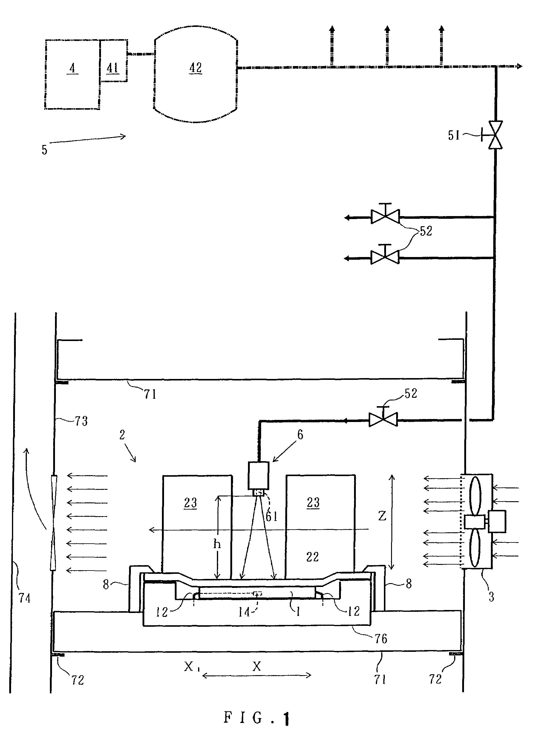
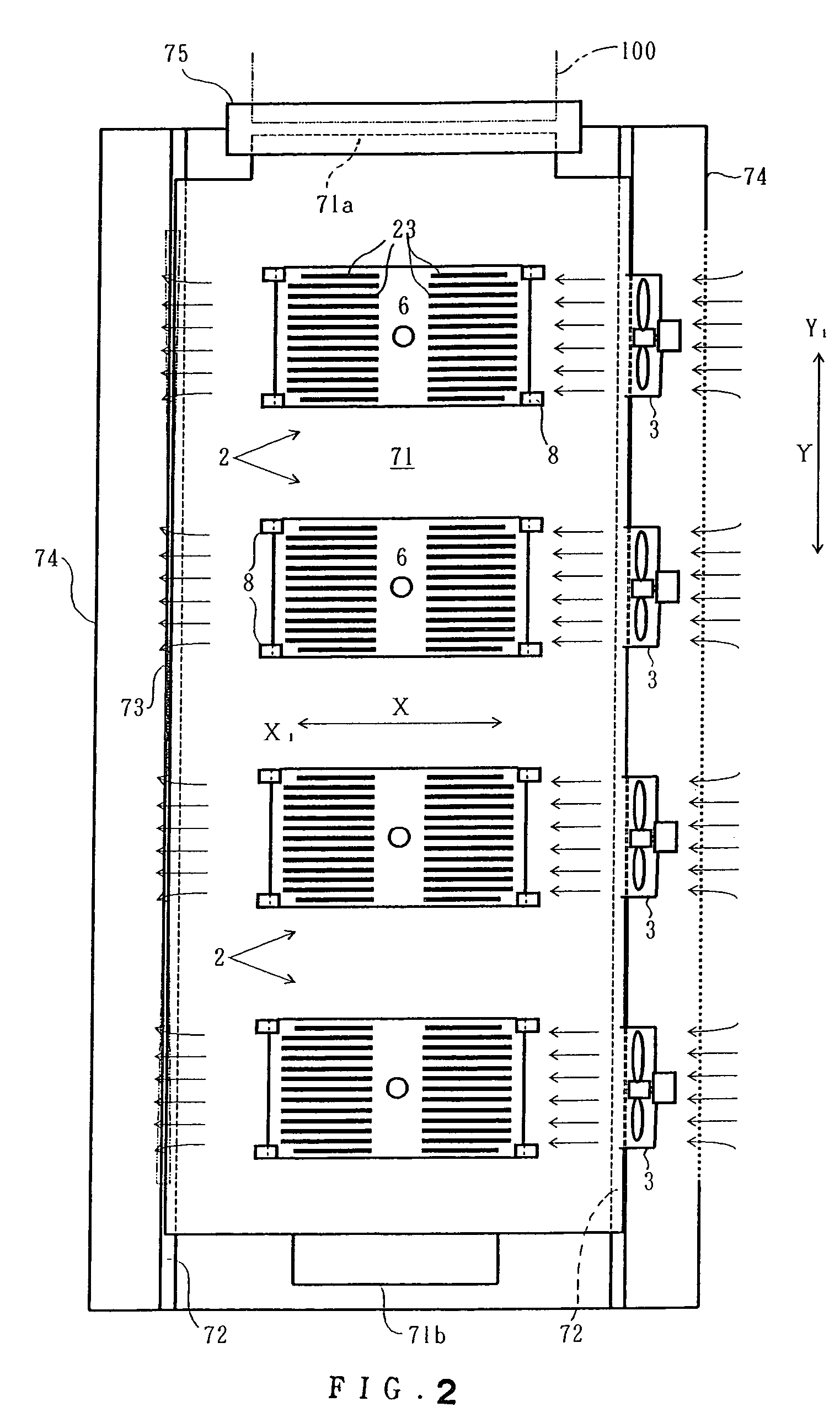
[0041]FIGS. 1 and 2 show examples of the entire structure of the cooling apparatus employing the present invention. FIG. 3 shows a configuration example thereof. FIGS. 1 and 2 show portions of one stage of the apparatus having a multistage configuration usually comprising 5-10 stages. Other stages are configured identically.

[0042]The cooling apparatus of the present example is an apparatus employed in a burn-in test of a device 1 that comprises an upper surface 11, in the present example a flat one surface, and that is formed so that it generates heat when electric current is passed therethrough up to a temperature higher than a temperature t, in the present example about 150° C., as the target temperature, and the temperature of the upper surface 11 also rises accordingly, this cooling apparatus being capable of cooling the device 1 to the temperature t. This cooling apparatus comprises a cooling body 2, a blower 3 as an air supply means, a compressor 4 comprising a compressed air ...


PUM


Abstract

A cooling apparatus configured such that a cooling body provided with heat-dissipating plates is pressed against a device to which a socket of a burn-in board is attached, and air is provided by a blower such that the air passes between the heat-dissipating plates, and compressed air provided from a compressed air supply system is discharged by a nozzle so that it directly hits a portion of the cooling upper surface of the cooling body. By means of the cooling effects from these two types of air, a device generating a large amount of heat can be cooled with good temperature accuracy.

Description

BACKGROUND OF THE INVENTION[0001]The present invention relates to a cooling apparatus capable of conducting cooling so as to obtain the target temperature of a semiconductor device that comprises a plane-like surface and generates heat to above the target temperature and has the temperature of the one surface rising when electric current is passed therethrough.[0002]A burn-in apparatus for semiconductor devices (referred to hereinbelow as “devices”) is generally known in which a multiplicity of devices are mounted on burn-in boards, the boards are stacked in multiple stages in a temperature controlled chamber, electric current is passed through the devices, and hot air with a temperature adjusted to the fixed temperature, for example 125° C., is caused to flow parallel to the burn-in boards inside the chamber and circulate, while uniformly cooling the multiplicity of devices (see, for example, Patent References 1, 2). With such a burn-in apparatus, in the case of conventional device...

Claims


Application Information

Patent Timeline
Patent Type & Authority Patents(United States)
IPC IPC(8): F28B9/00
CPCH01L23/467H01L2924/0002H01L2924/00G01R31/26H05K7/20
Inventor SHIMADA, TETSUYAWATABE, KATSUHIKO
Owner ESPEC CORP
Why Eureka
Try Eureka