Electric power tool

a technology of electric power tools and power tools, which is applied in the direction of portable power-driven tools, dynamo-electric machines, portable percussive tools, etc., can solve the problems of increased production costs, reduced service life of percussion mechanisms, and insufficient robustness of the housing shell for operation on construction sites, etc., and achieves low energy consumption and simple manufacturing.

Active Publication Date: 2007-08-21
HILTI AG
View PDF12 Cites 18 Cited by
  • Summary
  • Abstract
  • Description
  • Claims
  • Application Information

AI Technical Summary

Benefits of technology

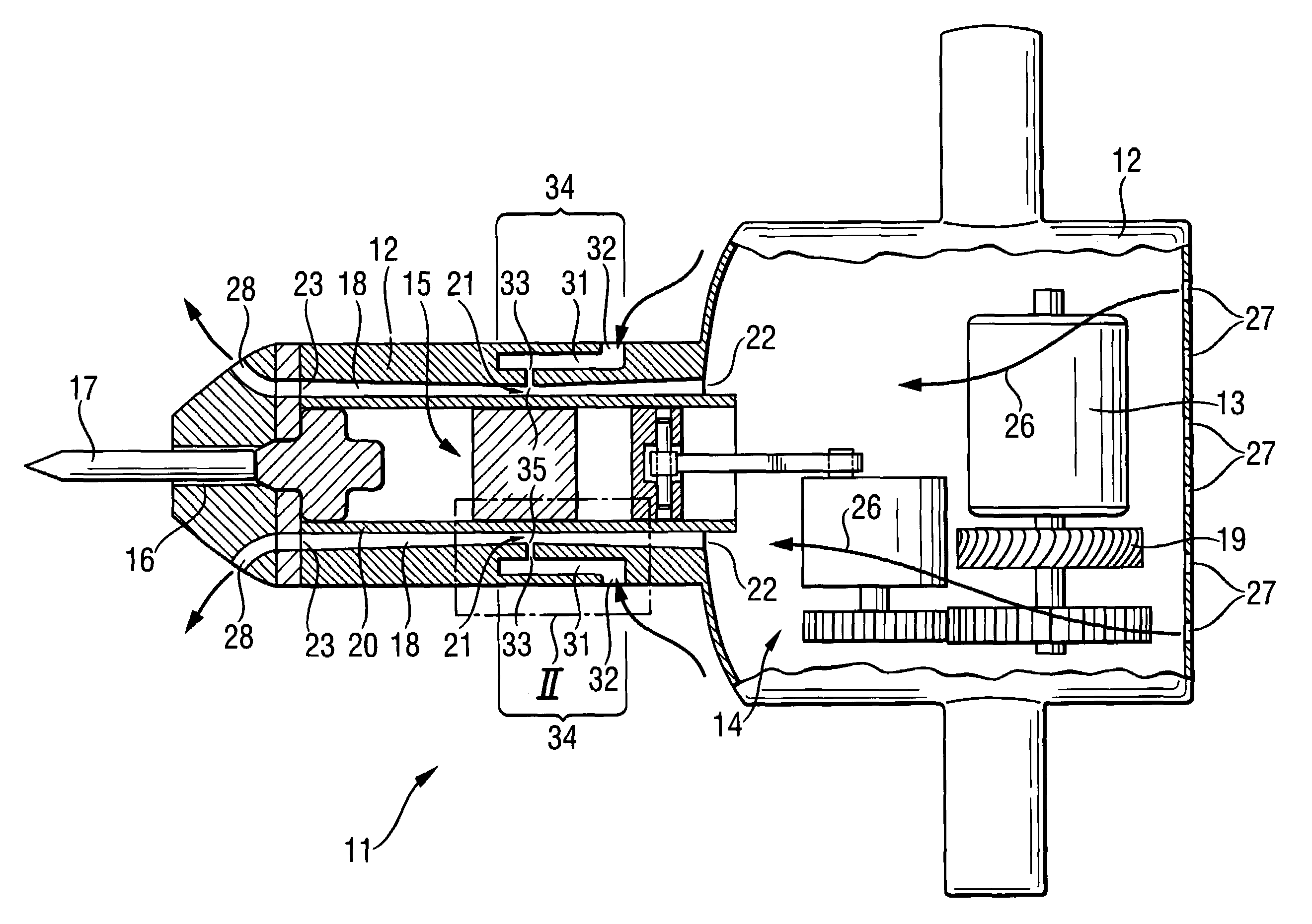
[0011]It is the object of the invention to provide an electric power tool with an percussion mechanism which is simple to manufacture and with a fan element advantageously having a low energy consumption which ensures the cooling of the entire electric power tool and the percussion mechanism in particular.
[0013]Because of the constriction or tapering of the cooling air channel, a static pressure lying below the barometric ambient pressure outside the at least one intake opening is achieved (similar to a venturi nozzle) at the location where the connection opening of the fresh air channel is arranged. Due to the low pressure that is generated, surrounding air is passively sucked in through the fresh air channel and is carried to the blow-off openings via the cooling air channel. The intake of fresh air through the fresh air channel and the cooling of the heated cooling air that flows past in the cooling air channel is carried out without arranging additional fan elements or forming multi-channel cooling air flows to the fan element on the delivery side of the fan element or downstream of the fan element. The temperature of the cooling air flow heated by the rest of the heat-generating components is substantially reduced. Although the percussion mechanism is at the end of the cooling chain, the service life of the percussion mechanism is prolonged as a result of the passive feed of fresh air and the resulting reduction in temperature of the cooling air flow in the region of the percussion mechanism because the lubricating spaces and sealing spaces are exposed to less thermal stress. Further, the contact temperature is decreased in the region of the percussion mechanism to a tolerable level so that no further design steps such as the arrangement of additional housing shells are required to improve the user-friendliness of the electric power tool or to meet authorized standards.
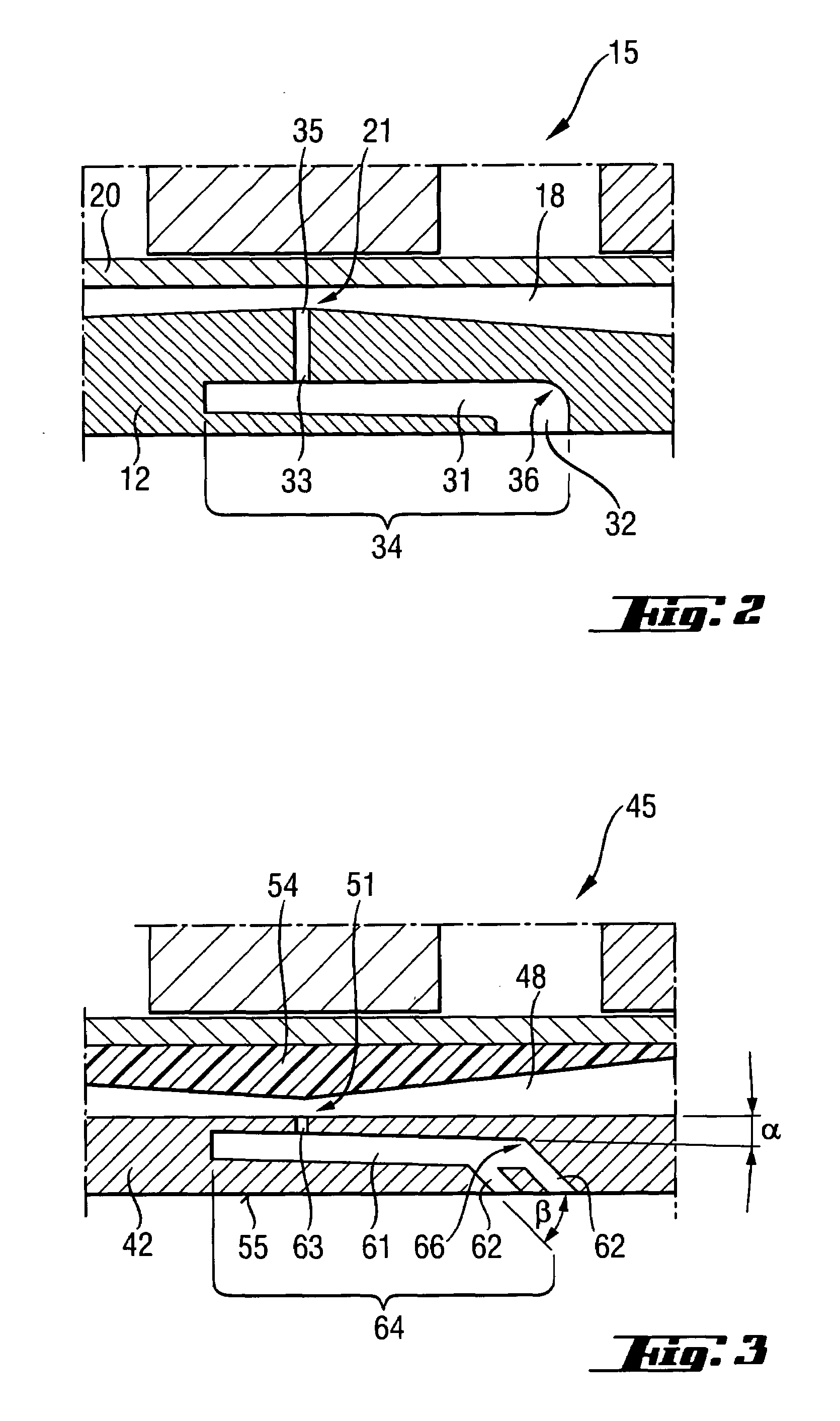
[0014]The cross-section of the cooling air channel preferably decreases steadily or continuously from at least one end of the cooling air channel to the constriction, where the cross-section of the cooling air channel is most narrow, so that the loss of flow within the cooling air channel is kept low in spite of the constriction of the cross-section of the cooling air channel. The constriction of the cross-section of the cooling air channel advantageously increases continuously from the end of the cooling air channel upstream of the cooling air flow and, after the connection opening opens into the cooling air channel, decreases again continuously until the other end of the cooling air channel downstream of the cooling air flow. Further, the surfaces of the corresponding channel portions have smoother walls particularly in the region of the constriction where a high flow velocity prevails so as to minimize unwanted loss of pressure.
[0016]The connection opening is preferably smaller than the intake opening so as to support the passive intake of surrounding air through the fresh air channel by means of the cooling air flowing in the cooling air channel. This ensures an even better cooling of the percussion mechanism. In addition, the cross-section of the connection opening is advantageously substantially smaller than the cross-section in the area of the constriction of the cooling air channel. Further, an advantageous intake behavior is achieved when the connection opening is sharp-edged, but without burrs, at its mouth. Instead of arranging the at least one intake opening perpendicular to the outer side of the external housing, it can also be arranged diagonally at an angle between 0° and 90° to the outer side of the external housing. The connection opening need also not necessarily extend in perpendicular orientation to the longitudinal extension of the cooling air channel. In order to minimize flow losses, rounded or angularly slanting deflections are advantageously formed.
[0017]The fresh air channel preferably has a portion extending substantially parallel to the cooling air channel so that removed material or dust occurring during operation cannot penetrate directly into the cooling air channel. In addition, a portion extending substantially parallel to the cooling air channel can be manufactured in a simple manner.
[0018]At least one fresh air channel is preferably associated with each cooling air channel so that a sufficient amount of cool surrounding air can be supplied and a sufficient cooling of the percussion mechanism can accordingly be ensured.

Problems solved by technology

The known solution is disadvantageous in that the additional housing shell is not always sufficiently robust for operation on a construction site and often has special design requirements.
There are also additional production costs.
This known solution is disadvantageous in that the percussion mechanism is located at the end of the cooling chain and the cooling air has already been heated by the other heat-generating component parts of the electric power tool.
The service life of the percussion mechanism is reduced because critical lubricating space and sealing space is thermally overloaded.

Method used


Image

  • Electric power tool
  • Electric power tool
  • Electric power tool

Examples


Embodiment Construction

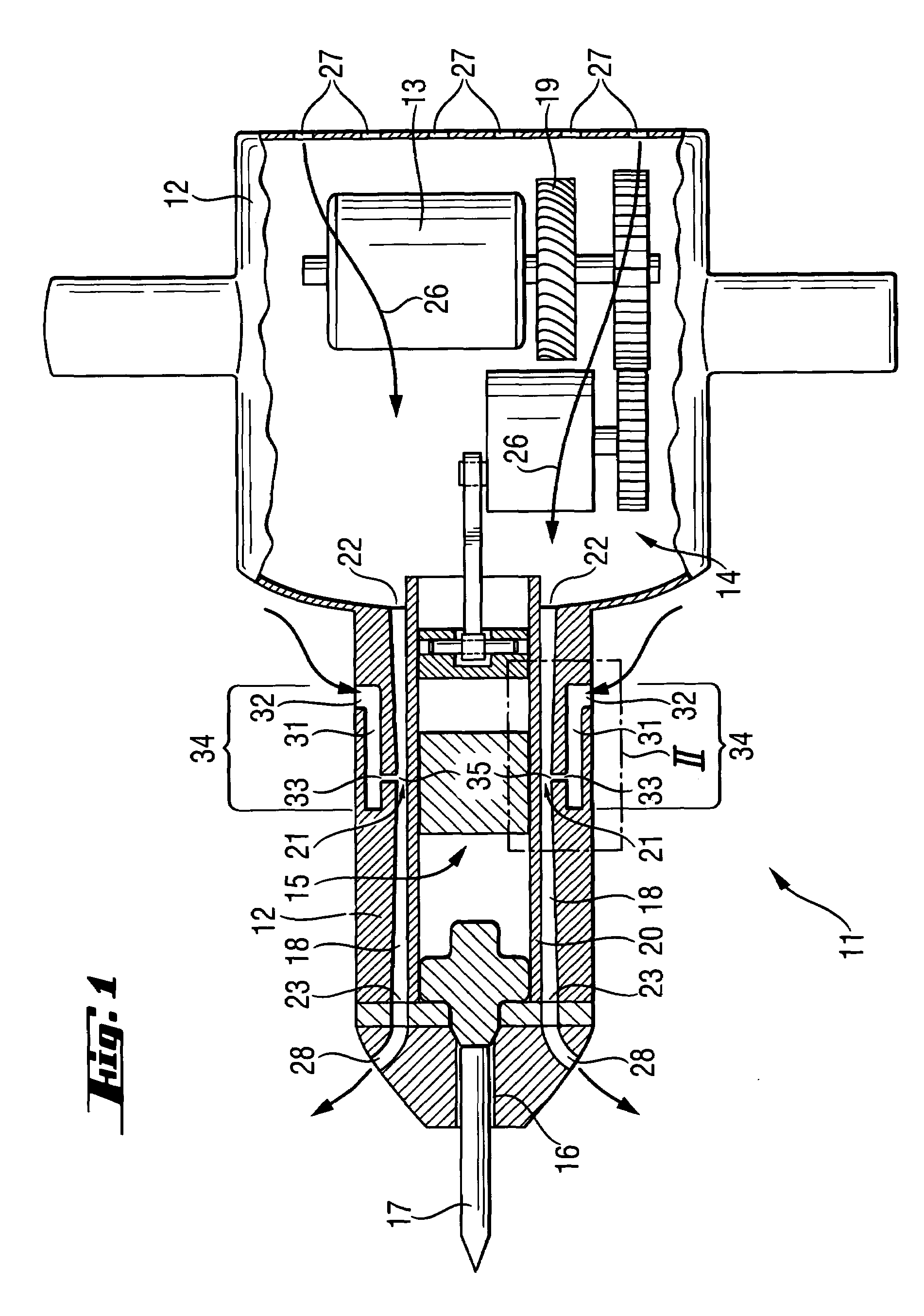
[0026]The electric power tool 11 shown in FIGS. 1 and 2 is a chisel hammer with an external housing 12 in which a driving motor 13 and an percussion mechanism 15 are provided. The percussion mechanism 15 communicates with the driving motor 13 via a gear unit 14 for percussive driving of a working tool 17 which can be secured in a tool holder 16. The housing 20 of the percussion mechanism 15 is made from an extruded profile and has cooling air channels 18 extending along the longitudinal extension of the percussion mechanism 15. A fan element 19 driven by the driving motor 13 is provided in the external housing 12 for generating a cooling air flow 26.

[0027]Further, fresh air channels 31 are associated with every cooling air channel 18. The fresh air channels 31 communicate with the atmosphere via an intake opening 32 in the external housing 12, on the one hand, and communicate with the cooling air channel 18 via a connection opening 33, on the other hand. Each of the fresh air channe...


PUM

PropertyMeasurementUnit
angleaaaaaaaaaa
angleaaaaaaaaaa
areaaaaaaaaaaa

Abstract

An electric power tool includes a percussion mechanism (15) located in an external housing (12) of the power tool (11) and driven by a driving motor (13) connected with the percussion mechanism (15) by a gear unit (14). An arrangement for cooling the power tool (11) includes a fan element (19) located in the external housing for generating a cooling air flow (26), a cooling air channel (18) extending along a longitudinal extent of the percussion mechanism (15) and a cross-section of which has a constriction (21; 51), a fresh air channel (31; 61) having an intake opening (32; 62) for communicating with atmosphere and formed in the external housing (12; 42) and a connection opening (33; 63) for communicating with the cooling air channel (18; 48) and arranged in an area of the constriction (21: 51) of the cooling air channel (18; 48).

Description

BACKGROUND OF THE INVENTION[0001]1. Field of the Invention[0002]The present invention relates to an electric power tool, particularly a chisel hammer, drill hammer or combination hammer, and including an external housing, a percussion mechanism arranged in the external housing, a motor for driving the percussion mechanism, a gear unit for connecting the driving motor with the percussion mechanism, and means for cooling the driving motor and the gear unit and including a fan element located in the external housing for generating a cooling air flow in the external housing, and a cooling air channel extending along a longitudinal extent of the percussion mechanism.[0003]2. Description of the Prior Art[0004]When operating electric power tools of the type mentioned above, the driving motor, percussion mechanism, gear units, and any existing electronics, as heat-generating components, generate heat that must be removed in order to prevent overheating of the electric power tool and of the ...

Claims


Application Information

Patent Timeline
Patent Type & Authority Patents(United States)
IPC IPC(8): B25D17/20
CPCB25D17/20B25D2211/003B25D2211/068B25D2217/0061B25F5/008
Inventor HAMMERSTINGL, STEFANRUNAU, BERND
Owner HILTI AG
Why Eureka
Try Eureka