Inlet vane for centrifugal particle separator

a centrifugal particle and separator technology, applied in the direction of liquid fuel engines, separation processes, combustion air/fuel air treatment, etc., can solve the problems of reducing the separation efficiency of the precleaner, unsatisfactory air quality, and unsatisfactory air quality,

Active Publication Date: 2007-08-21
DREISON INT
View PDF17 Cites 52 Cited by
  • Summary
  • Abstract
  • Description
  • Claims
  • Application Information

AI Technical Summary

Problems solved by technology

Undesirable contaminants in the atmosphere include particulate matter such as dirt, dust, sand, snow and the like.
As the velocity of air flow decreases, the centrifugal force on the contaminants also decreases reducing the separation efficiency of the precleaner.
This necessitates a particle separator of an undesirably large axial and circumferential volume, having a narrow operational flow range and less than optimum separation efficiency.

Method used


Image

  • Inlet vane for centrifugal particle separator
  • Inlet vane for centrifugal particle separator
  • Inlet vane for centrifugal particle separator

Examples


Embodiment Construction

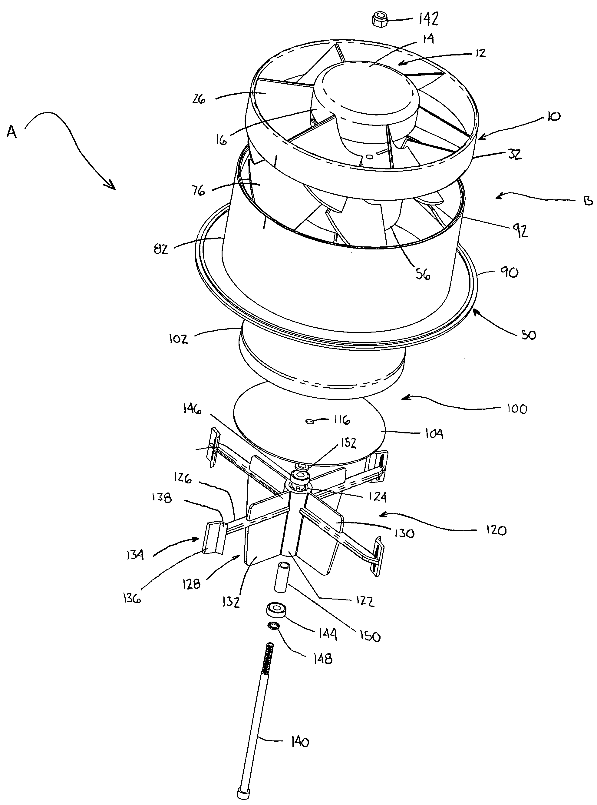
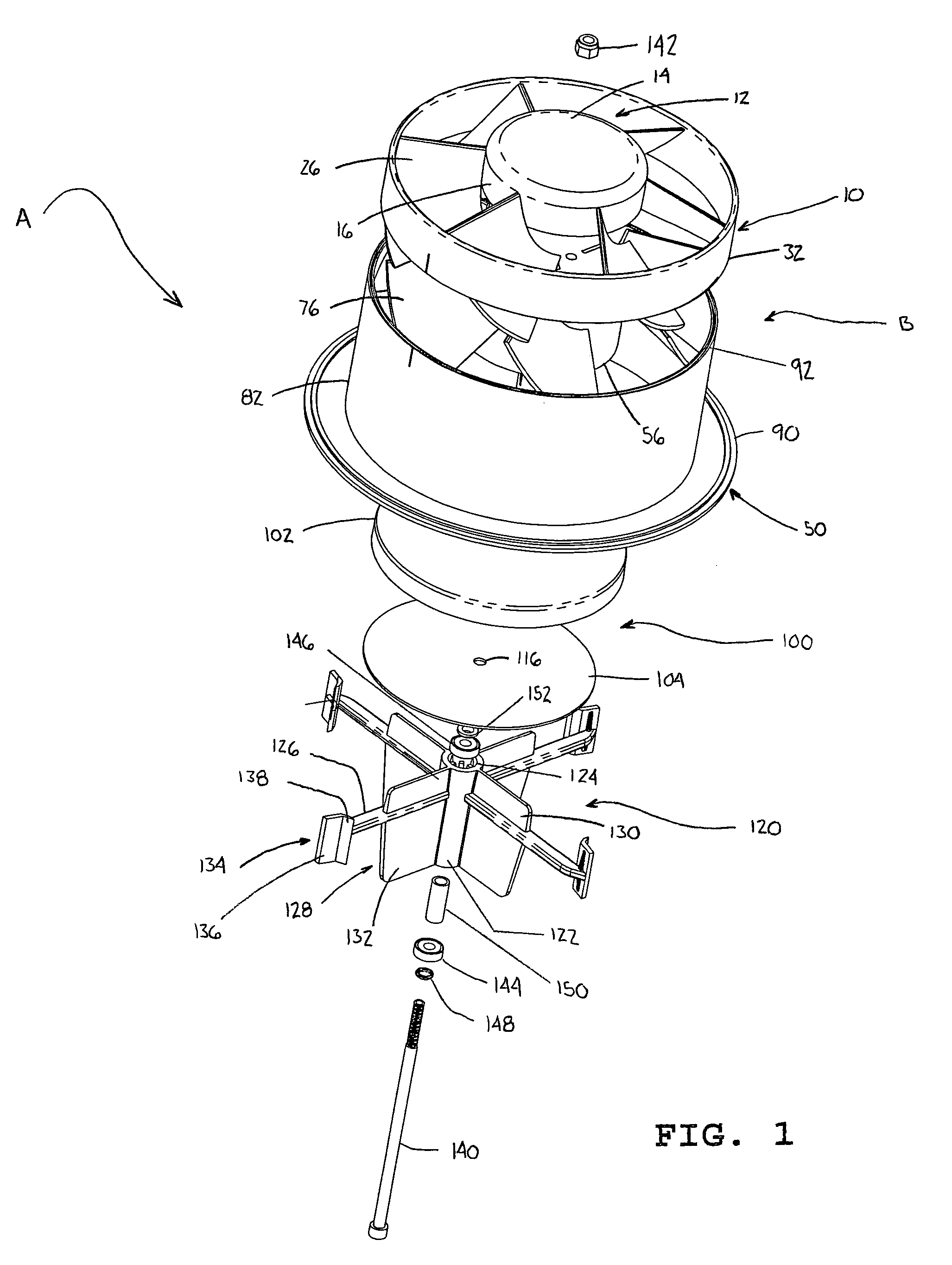
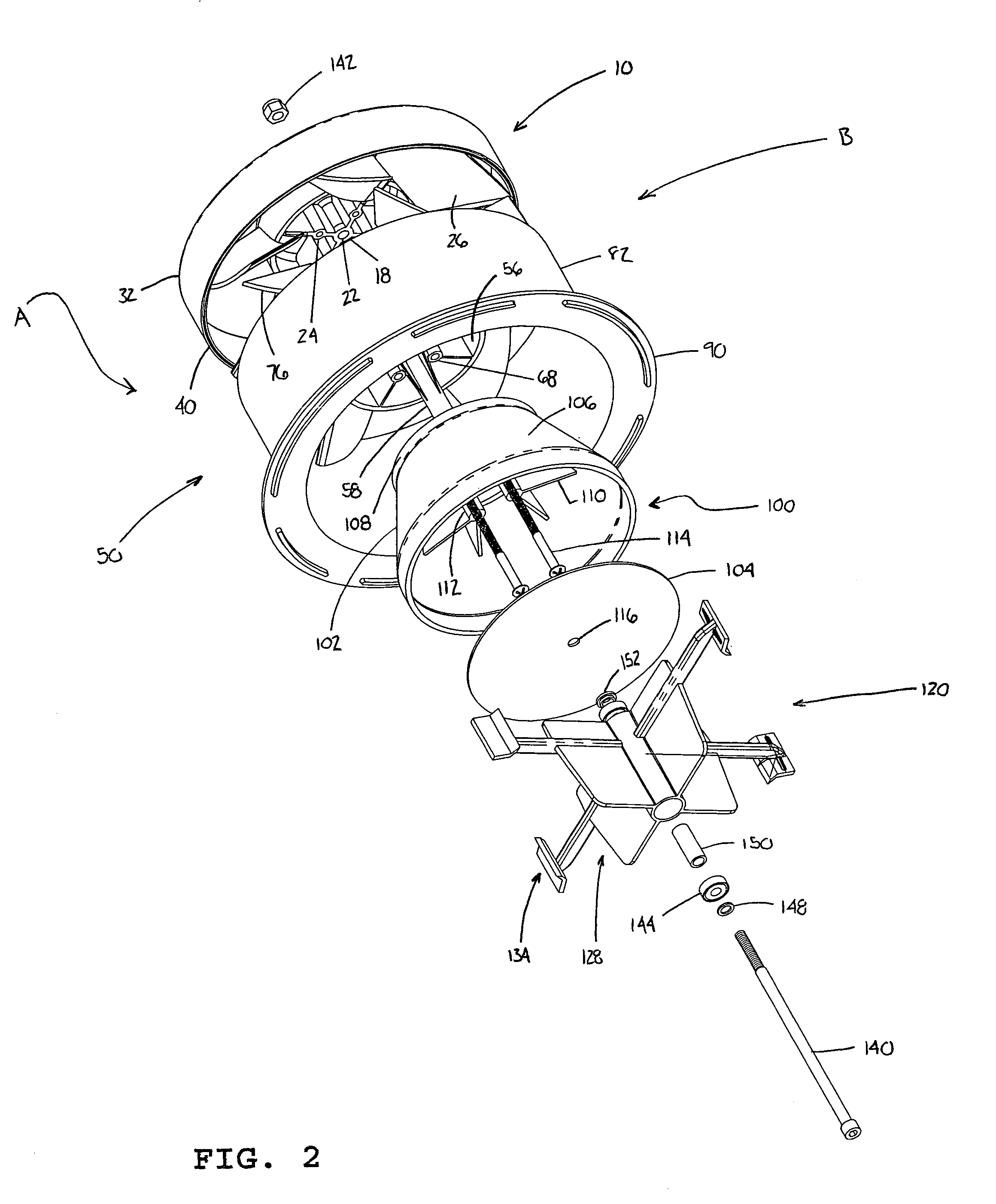
[0027]Referring now to the drawings, wherein the showings illustrate the preferred embodiments of the invention only and are not intended to limit same, FIGS. 1 and 2 show an air precleaner assembly A including a centrifugal particle separator B in accordance with a first embodiment of the present invention. While the centrifugal particle separator is shown as part of an air precleaner assembly, it should be appreciated that the present invention can be used in various applications which operate on the principal of centrifugal separation to remove contaminants from air. The air precleaner assembly includes the centrifugal particle separator B comprising a first vane assembly 10 and a second vane assembly 50; a masking assembly 100; and a rotating impeller assembly 120.

[0028]In this embodiment, the first vane assembly 10 is mounted atop the second vane assembly 50 because the air precleaner assembly A is orientated along a vertical axis. Therefore, the first vane assembly 10 will be ...


PUM

PropertyMeasurementUnit
lengthaaaaaaaaaa
speedaaaaaaaaaa
air flow velocityaaaaaaaaaa

Abstract

A centrifugal particle separator includes a first vane assembly and a second vane assembly. The first vane assembly includes a centrally positioned hub, a collar encircling the hub and a plurality of first vanes. Each first vane can have an inner end connected to the hub and an outer end connected to the collar, wherein a trailing edge of at least one of the plurality of first vanes can extend past an edge of the collar. The second vane assembly includes a centrally positioned hub, a collar encircling the hub and a plurality of second vanes circumferentially disposed about the hub. Each second vane can have an inner end connected to the hub and an outer end connected to the collar, wherein a leading edge of at least one of the plurality of second vanes can extend past an edge of the collar. When the first and second vane assemblies are secured together, at least one of the plurality of first vanes protrudes into the second vane assembly.

Description

BACKGROUND OF THE INVENTION[0001]The present invention generally pertains to centrifugal particle separators. More particularly, the invention relates to a construction which improves the functional, structural and volumetric characteristics of molded or cast inlet vane assemblies of centrifugal particle separators.[0002]Generally, air precleaners are used for removing particulates from the air prior to introducing the air through an air cleaner or filter of an internal combustion engine. The function of the air precleaner is to remove as many contaminants from the air as possible before it flows into an air filter medium upstream from the internal combustion engine.[0003]Precleaners operate on the principle of centrifugal separation. Outside air, with its entrained contaminants, is drawn into the precleaner by the vacuum created by the engine. The air and contaminants traverse a set of fixed, static, vanes which cause the air to circulate at a great speed. Centrifugal force throws ...

Claims


Application Information

Patent Timeline
Patent Type & Authority Patents(United States)
IPC IPC(8): B01D45/12
CPCF02M35/022
Inventor EUBANK, GERRY E.DINGESS, ROBERT
Owner DREISON INT
Why Eureka
Try Eureka