Gas supplying method and system

a gas supply and gas technology, applied in the direction of liquid transfer devices, packaging, special dispensing means, etc., can solve the problems of significant lowering of rare gas purity, difficult to efficiently carry out the separation of a targeted component gas, and increasing the amount of rare gas used, etc., to achieve efficient separation and purification

Active Publication Date: 2007-08-21
OHMI +1
View PDF10 Cites 81 Cited by
  • Summary
  • Abstract
  • Description
  • Claims
  • Application Information

AI Technical Summary

Benefits of technology

[0012]An object of the present invention is to provide a gas supplying method and system in which effective component gas, such as a rare gas, contained in exhaust gas discharged from a semiconductor product manufacturing process, etc., can be separated and purified efficiently to be resupplied regardless of variation in the flow rate or composition of the exhaust gas and consumed gas can be replenished efficiently.
[0013]In order to achieve the above object, the gas supplying method according to the present invention is characterized in that, in a method for collecting exhaust gas discharged from a gas using facility, separating / purifying effective component gas contained in the exhaust gas and supplying the effective component gas thus obtained to the gas using facility, the exhaust gas discharged from the gas using facility is added with a replenishing gas of the same components as the effective component gas and then the effective component gas is separated and purified. In particular, the present invention is characterized in that the above-mentioned replenishing gas is added to the exhaust gas so that the component ratio of the gas to be separated and purified becomes constant.

Problems solved by technology

In these methods, however, since a system is designed in accordance with a predetermined flow rate and composition of a mixed gas, a predetermined flow rate and degree of purity of a targeted component gas to be recovered, and so forth, it is difficult to efficiently carry out the separation of a targeted component gas.
As described above, if a conventional PSA system is used to separate and purify a target gas, for example, effective component gas, such as a rare gas, from an exhaust gas whose flow rate and concentration change from time to time, problems such as significant lowering in purity of collected rare gas due to unstable operational state and uneven recovery rate of a rare gas may be caused since the amount of exhaust gas introduced and the amount of product gas collected vary.
Accordingly, there is a problem in that a large amount of rare gas is initially required, and hence, the amount of rare gas used will increase, increasing the effective gas cost.

Method used


Image

  • Gas supplying method and system
  • Gas supplying method and system
  • Gas supplying method and system

Examples


example 1

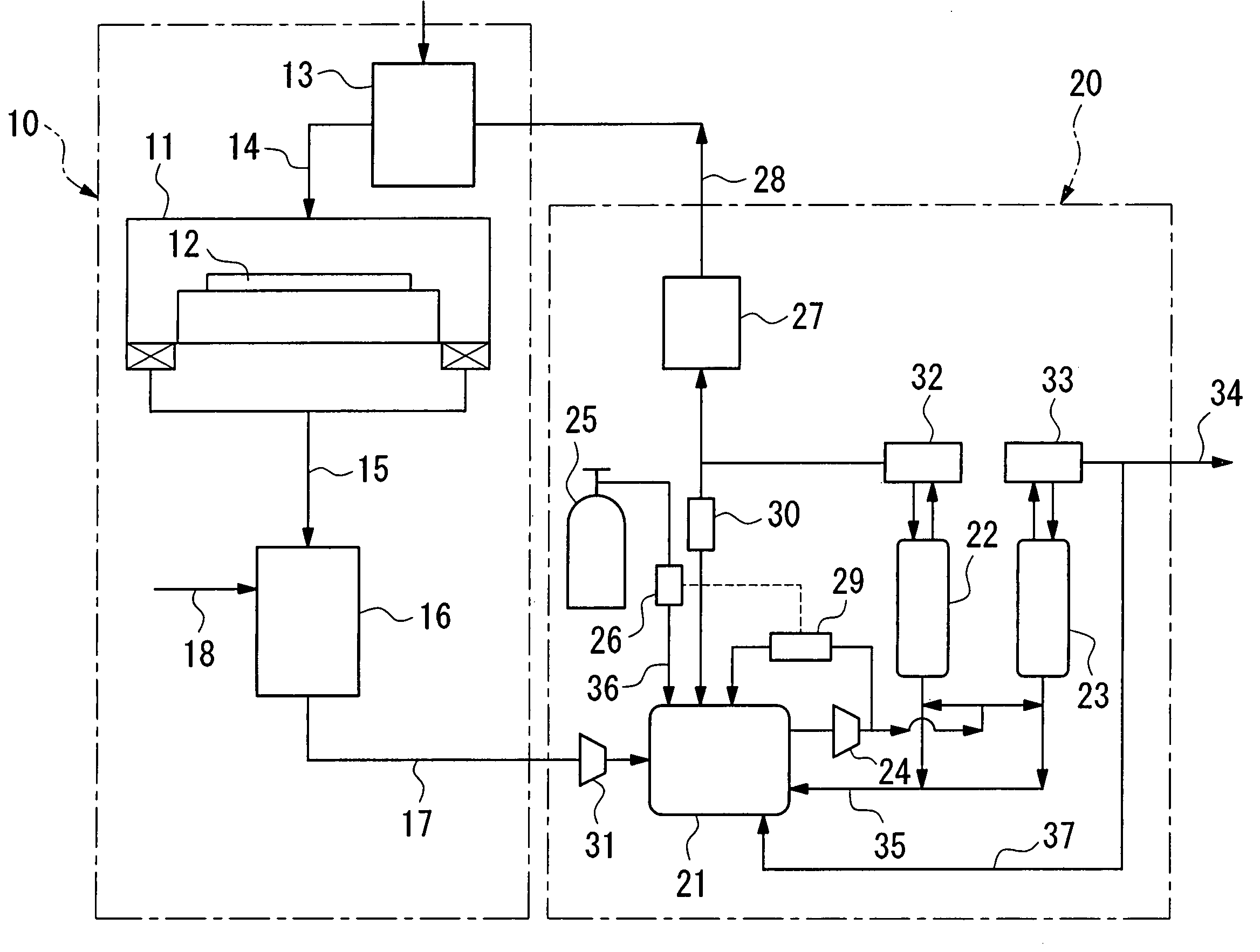
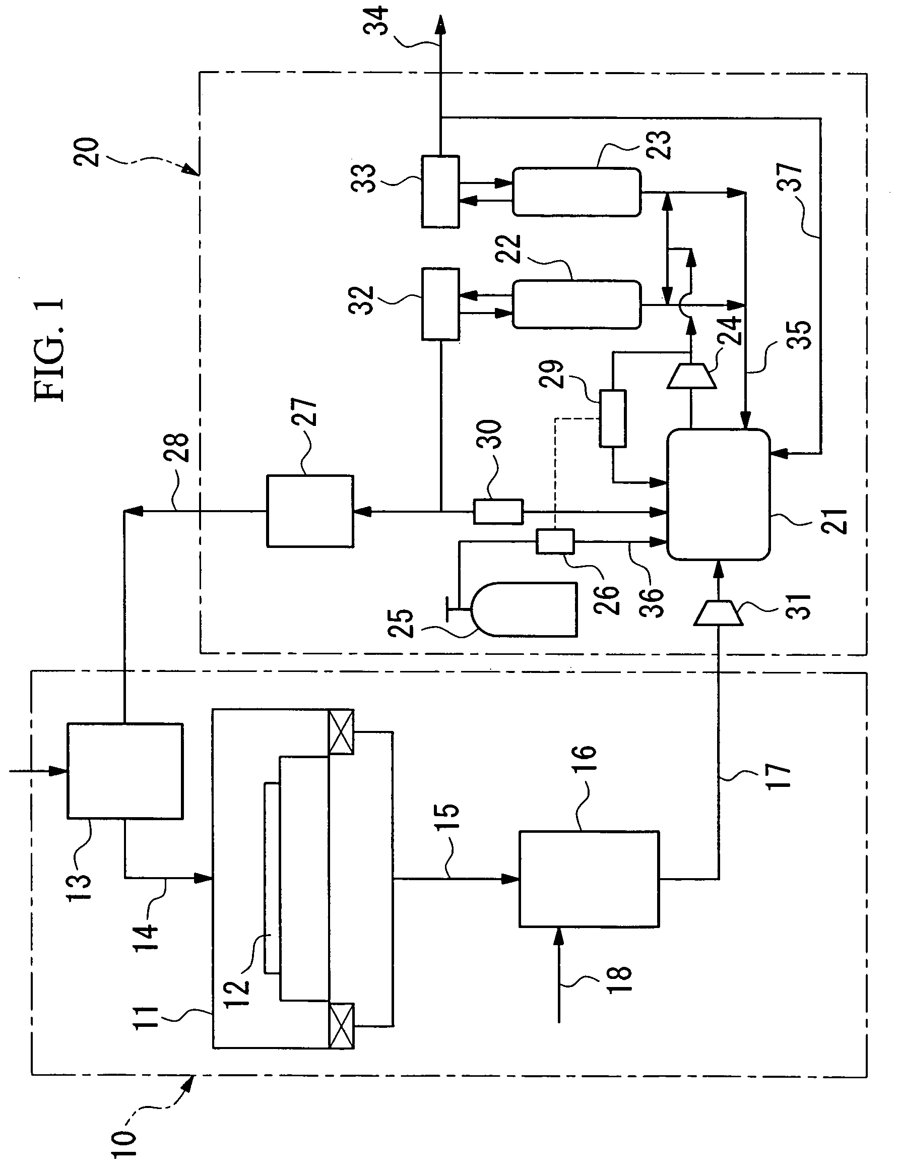
[0042]In a gas supplying system having a structure shown in FIG. 1, 6.5 kg of Zeolite 4A was filled in the first adsorption tower 22 having an inner diameter of 156 mm and a filling height of 500 mm, and 2 kg of activated carbon was filled in the second adsorption tower 23 having an inner diameter of 92 mm and a filling height of 700 mm. A volume variable tank having a maximum volume of 100 L and a minimum volume of 20 L was used as the exhaust gas storage tank 21. Exhaust gas was introduced into the gas supplying device at a rate of 1 L / min for both nitrogen gas and krypton. The gas introduced into the adsorption tower was compressed to about 0.4 MPa using the compressor 24, and was introduced into each of the adsorption towers at a flow rate of about 22 L / min. A separation operation based on the PSA method was carried out at a process switching period of 200 seconds. The flow rate of the first adsorption tower outlet gas (krypton) and the second adsorption tower outlet gas (nitrog...

example 2

[0044]The flow rate and composition of the exhaust gas introduced into the gas supplying system were varied using the same gas supplying system as in Example 1. First, after exhaust gas with a flow rate of nitrogen of 1 L / min and krypton of 350 cc / min was introduced and stored in the exhaust gas storage tank 21, it was introduced into the adsorption tower in the same manner as described above and a recovery operation for krypton was performed. At that time, the flow rate of krypton in the first adsorption tower outlet gas was about 350 cc / min and the ratio of krypton in the gas introduced into the adsorption tower was stable at about 49%.

[0045]After maintaining this state for about 5000 seconds, while maintaining the flow of nitrogen gas at 1 L / min, krypton was supplied for twenty minutes at a flow rate of 350 cc / min and then the supply of krypton was stopped for 10 minutes. This cycle of supplying krypton was repeated for nine times. After a time delay of about 600 seconds, the flo...

example 3

[0046]The stability over a long period was confirmed using the same gas supplying system as in Example 1. The inside volume of the krypton cylinder 25 was 3.4 L, and 680 L (at atmospheric pressure) of krypton was filled therein. The flow controller 26 was operated to replenish krypton so that the ratio of krypton in the gas introduced into the adsorption tower measured by the component detector 29 became 55%. After about 1000 hours of continuous operation, the amount of consumed krypton was measured based on the decrease of pressure inside the krypton cylinder 25 and it was found to be about 123 L (converted to atmospheric pressure). Since the actual annual operation time in hours of the plasma oxidation device 10, which was calculated based on the average rate of operation, is about 5000 minutes, it is understood, by combining the above-mentioned gas supplying devices, that it is not necessary to replace the krypton cylinder for one year if a krypton cylinder having a volume of 3.4...


PUM

PropertyMeasurementUnit
pressureaaaaaaaaaa
pressureaaaaaaaaaa
inner diameteraaaaaaaaaa

Abstract

Gas supplying method and system in which effective component gas in exhaust gas can be separated and purified efficiently to be resupplied regardless of variation in the flow rate or composition of the exhaust gas and consumed gas can be replenished efficiently. In a method for collecting exhaust gas discharged from a gas using facility, separating / purifying effective component gas contained in the exhaust gas and supplying the effective component gas thus obtained to the gas using facility, the exhaust gas discharged from the gas using facility is added with a replenishing gas of the same components as the effective component gas before the effective component gas is separated and purified.

Description

[0001]This application is the U.S. national phase of international application PCT / JP02 / 12703 filed in Japanese on Dec. 4, 2002, which designated the U.S. PCT / JP02 / 12703 claims priority to JP Application No. 2001-369905 filed Dec. 4 2001. The entire contents of these applications are incorporated herein by reference.TECHNICAL FIELD[0002]The present invention relates to methods and systems for supplying gases. In particular, the present invention relates to a method and a system for supplying a gas in which effective component gas contained in an exhaust gas discharged from a gas using facility is separated and purified and is resupplied to the gas using facility.[0003]The present application is based on Japanese Patent Application No. 2001-369905, the contents of which are incorporated herein by reference.BACKGROUND ART[0004]In a process for manufacturing semiconductor products, such as semiconductor integrated circuits, liquid crystal panels, solar batteries and panels thereof, and...

Claims


Application Information

Patent Timeline
Patent Type & Authority Patents(United States)
IPC IPC(8): B01D53/00B01D46/00B01D53/34B01D53/04B01D53/46B01D53/68B01D53/70B01D53/74B01D53/81B01J4/00C01B23/00C23C16/44
CPCB01D53/46B01D53/68B01D53/70B01D53/74C01B23/001C01B23/0052B01D2257/11C01B2210/0042C01B2210/0029C01B2210/0035B01D2257/2066Y02P20/151B01D46/00
Inventor OHMIISHIHARA, YOSHIONAKAMURA, AKIHIRO
Owner OHMI
Why Eureka
Try Eureka