
Anti-glare film, method of producing the same, and display equipped with the same

a technology of anti-glare film and anti-glare film, which is applied in the direction of screws, threaded fasteners, instruments, etc., can solve the problems of high cost of anti-glare film produced by such a method, insufficient anti-glare function, and inability to achieve the effect of anti-glare function

Inactive Publication Date: 2007-08-21
SUMITOMO CHEM CO LTD
View PDF4 Cites 5 Cited by
  • Summary
  • Abstract
  • Description
  • Claims
  • Application Information

AI Technical Summary

Benefits of technology

[0008]The present inventors have intensively studied to attain the above-mentioned object, and resultantly found that, on an anti-glare film having roughness formed on its surface, if the above-mentioned roughness is formed with suitable variation satisfying a specific condition, then, regular reflectance along the regular reflection direction against incidence light at given angle on the above-mentioned anti-glare film and the ratio of the reflectance against the above-mentioned incidence light, along a direction inclined by given angle or more toward the film side from the normal reflection direction, to the above-mentioned regular reflectance, are respectively in given ranges, and by this, the anti-glare function of the anti-glare film is improved and-generation of white browning and decrease in visibility due to light diffraction are sufficiently prevented, leading to completion of the present invention.
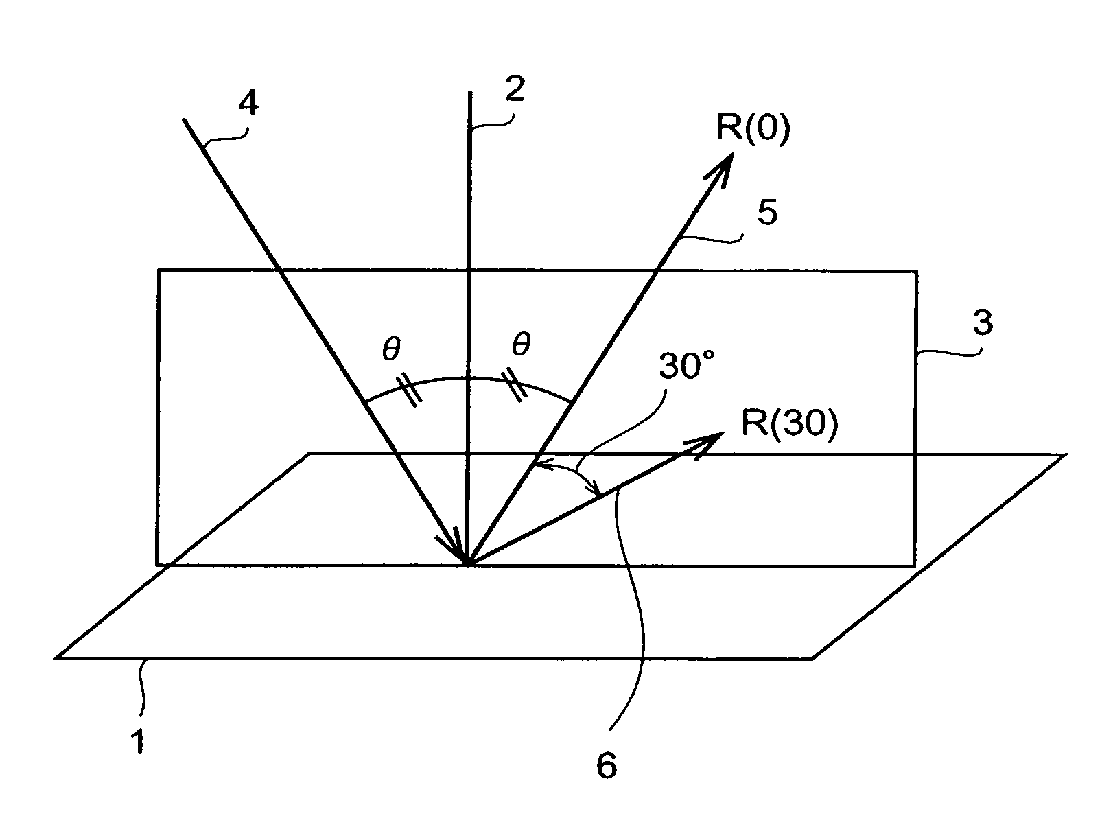
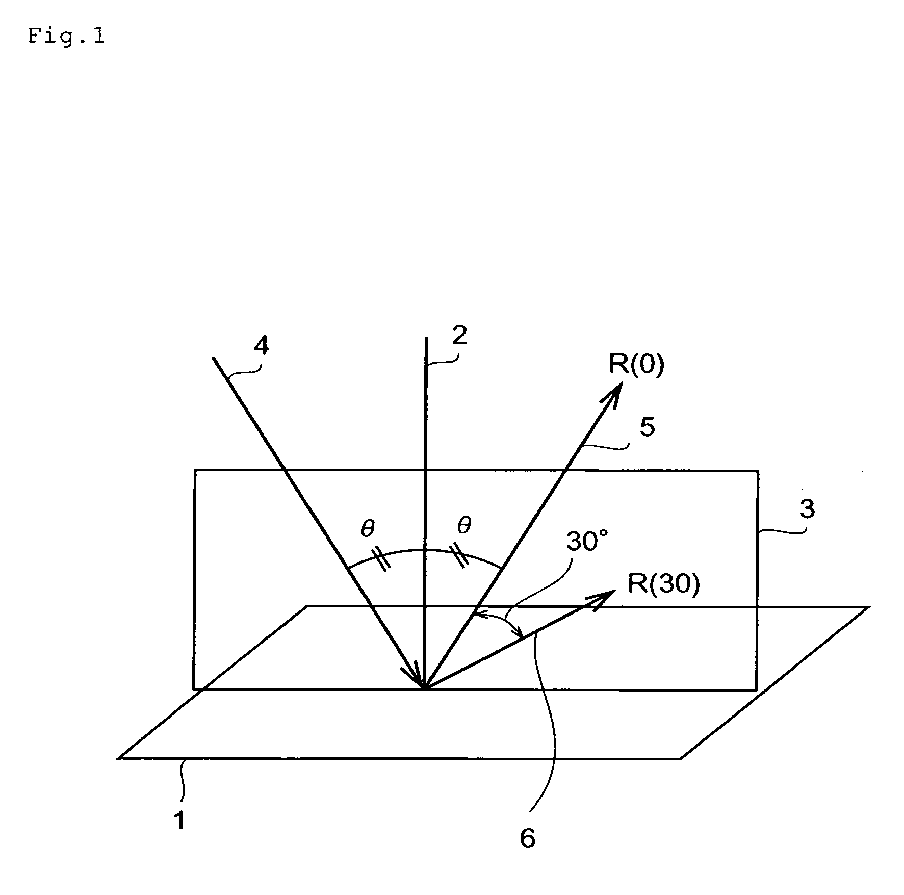
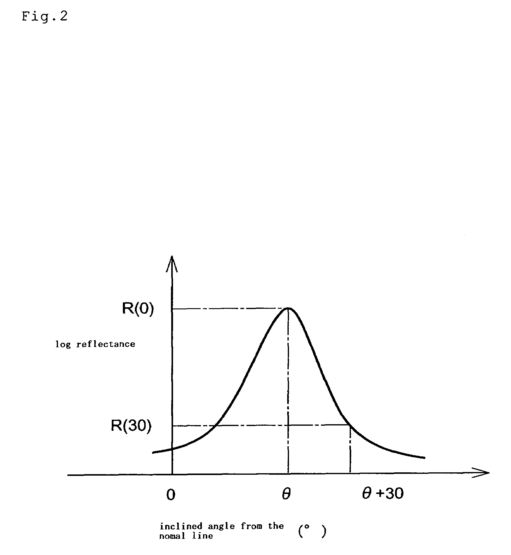
[0009]Namely, the anti-glare film of the present invention is an anti-glare film having rough surface of which R (0) is 1% or less, and R (30 or more) / R (0) is 0.001 or less, respectively, wherein R (0) is the regular reflectance along the regular reflection direction against incidence light at any angle from 5 to 30° from the normal line of the above-mentioned anti-glare film and R (30 or more) is the reflectance against the above-mentioned incidence light, along a direction inclined by 30° or more toward the above-mentioned anti-glare film side from the above-mentioned normal reflection direction. By satisfying such a condition, an anti-glare film can be obtained in which generation of white browning and decrease in visibility due to light diffraction are sufficiently prevented while maintaining an excellent anti-glare function.

Problems solved by technology

Of these, the former non-reflection film has high cost due to necessity of forming a multi-layer film of uniform optical membrane thickness.
However, an anti-glare film produced by such a method does not necessarily have roughness as intended and an anti-glare function is not obtained sufficiently since the location and form of irregularity of roughness are affected by the dispersed condition of a filler in a solvent, applied condition thereof, and the like.
Further, when such a conventional anti-glare film is placed on the surface of an image display, there is a tendency of generation of so-called white browning in which all display surface becomes totally whity because of scattering light and display shows turbid color.
However, even in the case of an anti-glare film obtained by forming roughness of regular disposition on a film as described above, light diffraction occurs due to the distribution of uniform distance between concave or convex lens and a film looks rainbow color to decrease the visibility of a display surface.

Method used


Image

  • Anti-glare film, method of producing the same, and display equipped with the same
  • Anti-glare film, method of producing the same, and display equipped with the same
  • Anti-glare film, method of producing the same, and display equipped with the same

Examples


example 1

[0075]First, 75 round apertures having a diameter (D) of 9 μm were provided in a region of 127 μm×127 μm so that the average value m1 of shortest distances between center coordinates of the apertures was 14.7 μm and the standard deviation σ1 of the shortest distances was 1.049. This was used as a unit cell, and several unit cells were placed at a period of 127 μm on the whole surface of a region of 80 mm×80 mm, to produced a two gradient photo-mask of 6 inch square.

[0076]Next, a positive photo-resist (manufactured by Tokyo Okasha K.K., trade name: PR13) was spin-coated on a glass plate giving a thickness of about 1.1 μm. The resulted glass plate with photo-resist was placed for 60 seconds on a hot plate heated at 110° C. for pre-bake. On this photo-resist, the above-mentioned photo-mask was kept so that the exposure gap was 180 μm (=L), and irradiated with light of g, h and i multi-line of a super high pressure mercury lamp as an exposure light source at a rate of 150 mJ / cm2 in term...


PUM

PropertyMeasurementUnit
Fractionaaaaaaaaaa
Fractionaaaaaaaaaa
Angleaaaaaaaaaa

Abstract

The present invention provides an anti-glare film having rough surface of which R (0) and R (30 or more) / R (0) are 1% or less and 0.001 or less, respectively, wherein R (0) is if the regular reflectance along the regular reflection direction against incidence light at any angle from 5 to 30° from the normal line of said anti-glare film and R (30 or more) is the reflectance against said incidence light, along a direction inclined by 30° or more toward said anti-glare film side from said normal reflection direction. And the present invention also provides the method of producing the above-mentioned anti-glare film.

Description

[0001]This U.S. application claims the priority benefit under 35 U.S.C. §119 of JP 2003-008744, filed Jan. 16, 2003, the complete disclosure of which is incorporated herein by reference.FIELD OF THE INVENTION[0002]The present invention relates to an anti-glare film, a method of producing the same, and a display equipped with the anti-glare film.BACKGROUND OF THE INVENTION[0003]Image displays such as liquid crystal displays, plasma display panels, CRT displays, organic EL displays and the like show remarkable deterioration in visibility when outer light is reflected in its display surface. For preventing such reflection of outer light, there is conventionally provided a film layer of preventing reflection of outer light on the surface of an image display, in televisions and personal computers in which image quality is valued, video cameras and distal cameras used outside under strong outer light, and portable telephones effecting display utilizing reflection light. This film layer is...

Claims


Application Information

Patent Timeline
IPC IPC(8): B32B3/26G02B1/11
CPCG02B1/11Y10S428/913Y10T428/24479Y10T428/24355Y10T428/12993F16B19/1036
Inventor KUWABARA, MASATOMAEDA, YASUTERU
Owner SUMITOMO CHEM CO LTD
Learn More