User input device

a user input and input device technology, applied in the field of signal processing, can solve the problems of not being able to recognise such sequence bits, tedious and time-consuming programming of the remote control device using the method, and not being able to control all such appliances

Inactive Publication Date: 2007-08-21
CANON AU
View PDF32 Cites 33 Cited by
  • Summary
  • Abstract
  • Description
  • Claims
  • Application Information

AI Technical Summary

Benefits of technology

[0030]It is an object of the present invention to substantially overcome, or at least ameliorate, one or more disadvantages of existing arrangements.

Problems solved by technology

However, such a remote control device adds the demand that all appliances controlled by the remote control device must use the protocol used by the remote control device.
Thus, a particular universal remote control device will generally be unable to control all such appliances.
The main disadvantage of the above ‘learning’ method is that programming the remote control device using the method is tedious and time consuming since a lot of keys need to be pressed.
Further, if the codes to be learned contain data that varies from message to message, such as sequence bits or numbers, then a remote control device using the learning method is not always able to recognise such sequence bits.
Thus, these bits are not able to be reproduced in the correct manner, by the remote control device, when re-transmitting the codes.
However, such a remote control device is limited as to the number of device codes that can be stored in the non-volatile memory.
Further, these stored device codes cannot be easily changed or replaced once the device codes have been loaded into the non-volatile memory.
Still further, the user interface of such a remote control device is fixed and cannot be readily changed according to the circumstances of use.
Firstly, a lot of data is required to program a universal remote control device with a particular range of functions that is required to operate a number of appliances remotely.
Such data is required since each button of a universal remote control device typically describes an entire transmission sequence for the particular button at a low level, leading to a lot of data repetition and redundancy.
The data repetition and redundancy raises the cost of manufacturing and purchasing such a remote control device since faster processors, more memory and more powerful batteries must be used to power such remote control devices.
Secondly, the user interface of a keypad based universal remote control device is fixed, and cannot be readily changed according to the circumstances of use.
Thirdly, software code stored on universal remote control devices cannot be easily changed.
Additionally, such remote control devices may not be able to be used with existing appliances that are not suitable configured.
Such a remote control device is simple to implement, but requires the user to go through an unintuitive protocol selection process, which can also interfere with other appliances.
While providing added versatility, this remote control device is limited to a fixed set of cards.
Further, the remote control device is limited to a fixed set of protocols, which are pre-installed on the remote control device.
Still further, this remote control device is limited to a predetermined fixed set of functions.
However, inaccuracies can result during this process which can prevent a protocol from being faithfully reproduced later.
Once such a reader has been configured for one particular set top box, the software code (i.e.,firmware) resident on the reader cannot be easily changed.
None of the existing smart card systems include a mechanism which is able to emulate conventional input devices such as a keyboard or mice, and which would enable a smart card used with such a system to work with existing applications without significant modification to the application.
The reader device of the existing smart card system discussed above, while containing an infrared transmitter, is unable to control the multitude of other appliances that use infrared remote control devices.
Finally, the reader device described above, while having the potential to operate in a variety of different modes, with different settings, does not provide a mechanism for operating modes and settings to be reconfigured as necessary by a user of the existing smart card system.
Accordingly, the reader device discussed above is generally limited in application to a predetermined number of pre-installed data transmission protocols.
These data transmission protocols cannot be easily changed and additional protocols cannot be easily added.
Further, the functionality of the reader device discussed above cannot be easily changed.

Method used


Image

  • User input device
  • User input device
  • User input device

Examples


example 1

[0477]A typical cable television operator has many subscribers using set-top boxes (e.g. the set top box 601). The set top boxes are typically supplied to subscribers from different manufacturers and each set top box typically employs a different set of communication protocols to receive keyboard, mouse and remote control input. In order to deploy readers similar to the reader 300, which will work with these varying set top boxes, without conflicting with other devices (e.g., VCRs, remote controlled doors, air conditioners etc), different infrared protocols must be used and installed as part of the firmware on the readers.

[0478]Most cable television operators would prefer to have a single model of reader, such as the reader 300, with the same firmware stored thereon. Such a reader 300 can be transported to the subscriber, on subscription to the network, together with a card 100F, as shown in FIG. 54. The card 100F is configured for selecting a transmission protocol to be used by the...

example 2

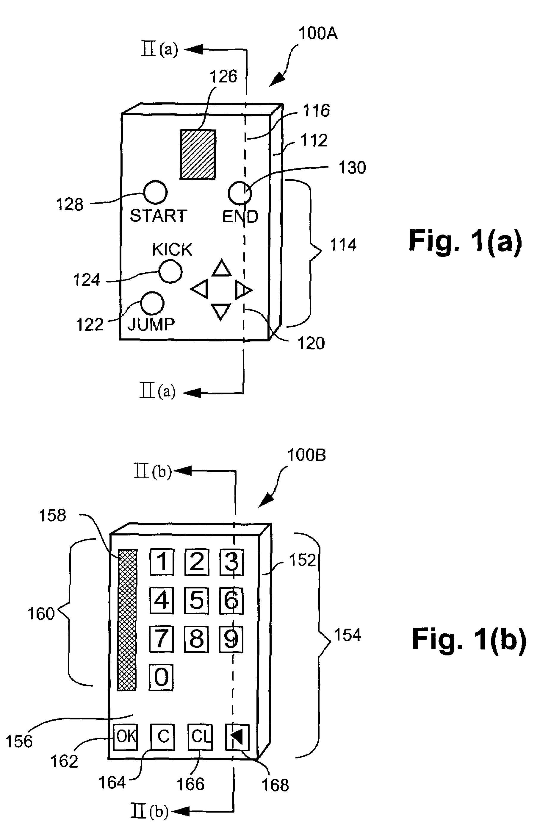
[0491]FIG. 29 shows an example of another card 100E, similar to the card 100F described above. However, the card 100E is configured for selecting a transmission protocol to be used by the reader 300 in the system 600 and in particular in the system 600B. User interface elements 2914 of the card 100E are in the form of a “SET GLOBAL” button 2901, a “LOAD” button 2903, a “TEST” button 2905 and a “DELETE” button 2907, printed on a front face 2916 of the card 100E, for each of four particular protocols (i.e., RC5, Control-S, NEC and R-MAP as known to those in the relevant art) of a reader 300 or system 600. The labels on each of the user interface elements suggest the function of each of the elements 114 and will not be described in detail.

[0492]In this example, similar to Example 1 above, a user is provided with the card 100E of FIG. 29. The card 100E includes protocol modules for each of a set of protocols (i.e., RC5, Control-S, NEC and R-MAP as known to those in the relevant art) sto...

example 3

[0496]In another example, an operator wishes to upgrade the set top boxes owned by subscribers, some of whom already own a reader 300, to a new type of set-top box (e.g. a new and improved Vx-2000 series set top box). A technician can be assigned to each of the subscriber's homes or offices to install the new set top boxes. Unfortunately, the new type of set top boxes use a different set of infrared communication protocols to the current set top boxes. Preferably, those subscribers who own a reader 300 would not be required to be issued with a different reader capable of communicating with the new set top box. Therefore, the technician carries a special card 100G, as seen in FIG. 55, which is configured to enable reconfiguration of the reader 300 to use the different set of infrared communications protocols as soon as the card 100G is inserted in the reader 300.

[0497]The card 100G is similar to the cards 100E and 100F, described above, and is configured for selecting the transmissio...


PUM


Abstract

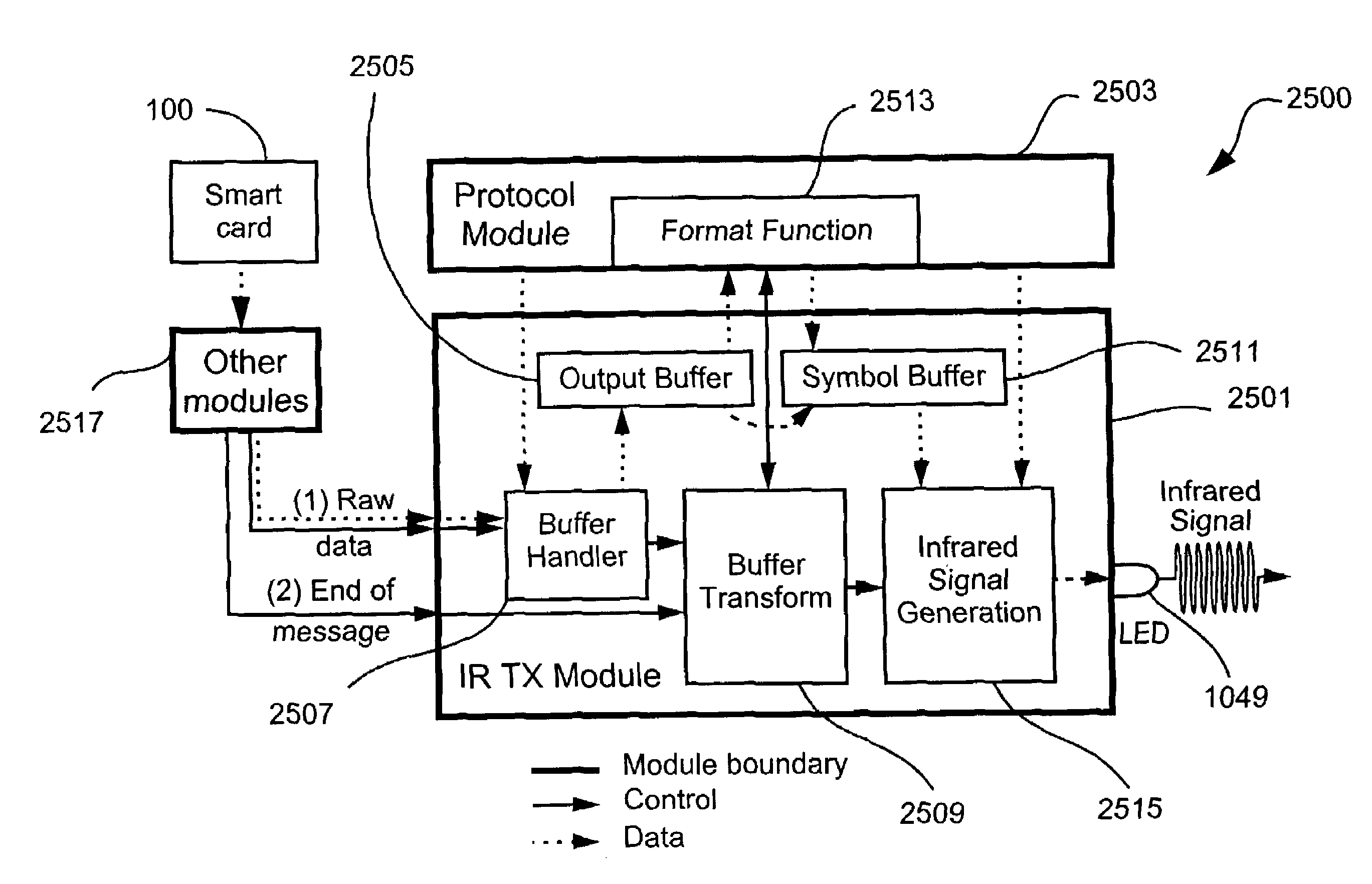
A user input device (300) configured with a communication protocol for communicating transmission data with predetermined apparatus (700, 601) is disclosed. The device (300) comprises a receiving means for receiving protocol data and an associated format function. The protocol data and the format function in combination describe a further communication protocol for communicating with the predetermined apparatus (700, 601). The device (300) also comprises a central processing unit (805) for selecting the received protocol data and the format function and for configuring the device (300) to communicate with the predetermined apparatus (700, 601). The protocol data defines properties of the further communication protocol and the format function is adapted to configure at least a portion of the transmission data for communication with the apparatus (700, 601) according to the further communications protocol.

Description

TECHNICAL FIELD OF THE INVENTION[0001]The present invention relates generally to the field of signal processing and, in particular, to a user input device.BACKGROUND[0002]Infrared (IR) remote control devices (or remote controls) are known, and can be used to control electronic appliances such as televisions, video recorders, stereo systems, set-top boxes, personal computers etc. For example, wireless keyboards and wireless mice can be used to operate a personal computer.[0003]Infrared data transmission in such remote control devices is typically achieved by alternating an Infrared Light Emitting Diode (LED) between two states (i.e., an OFF state and an ON state). In the OFF state, the LED is kept powered down and in the ON state, the LED is rapidly powered on and off at a predetermined frequency. This predetermined frequency is known as the ‘carrier frequency’.[0004]Several methods can be used to encode data based on the above-mentioned ON and OFF states. One such method is referred...

Claims


Application Information

Patent Timeline
Patent Type & Authority Patents(United States)
IPC IPC(8): G08C19/12G06F1/16G06F3/033G09G5/00H04N5/44
CPCG06F1/1626G06F1/1684G06F1/169G06F3/033H04N21/418H04N21/422H04N21/478H04N2005/4405G08C2201/21H04N21/42206
Inventor KISLIAKOV, ANDREW
Owner CANON AU
Why Eureka
Try Eureka