Log-periodic dipole array antenna

a dipole array and antenna technology, applied in the field of antennas, can solve the problems of unavoidable decrease in the affecting communication quality furthermore, and reducing the bandwidth and radiation efficiency of the conventional antenna, so as to achieve the effect of light weight, compact size and improved radiation efficiency

Inactive Publication Date: 2007-08-21
CORETRONIC
View PDF3 Cites 6 Cited by
  • Summary
  • Abstract
  • Description
  • Claims
  • Application Information

AI Technical Summary

Benefits of technology

[0006]Accordingly, the present invention is directed to provide a log-periodic dipole array antenna featuring increased broadband with a thin and compact-size, better margin to meet different bandwidth requirements.
[0008]Accordingly, for wider bandwidth, the present invention provides the log-periodic dipole array antenna by starting with the shape design of the antenna elements; therefore, the width of the antenna element is broadened gradually outwards from the side of the antenna element, which is connected to the corresponding symmetrical microstrip line. That is, the present invention can provide a better margin by changing the shape of the antenna elements for adjustment of broadband operations, and make the size of a log-periodic dipole array antenna with a lighter, thin and compact size.

Problems solved by technology

However, the bandwidth and the radiation efficiency of the conventional antenna are unavoidably decreased after the conventional antenna being minimized, and the transmission and the receiving of signals are relatively limited, and the communication quality furthermore affected.
In addition, how to increase the broadband or to provide a structure more suitable for miniaturization of the antenna has been a primary issue for the antenna design.

Method used


Image

  • Log-periodic dipole array antenna
  • Log-periodic dipole array antenna
  • Log-periodic dipole array antenna

Examples


Embodiment Construction

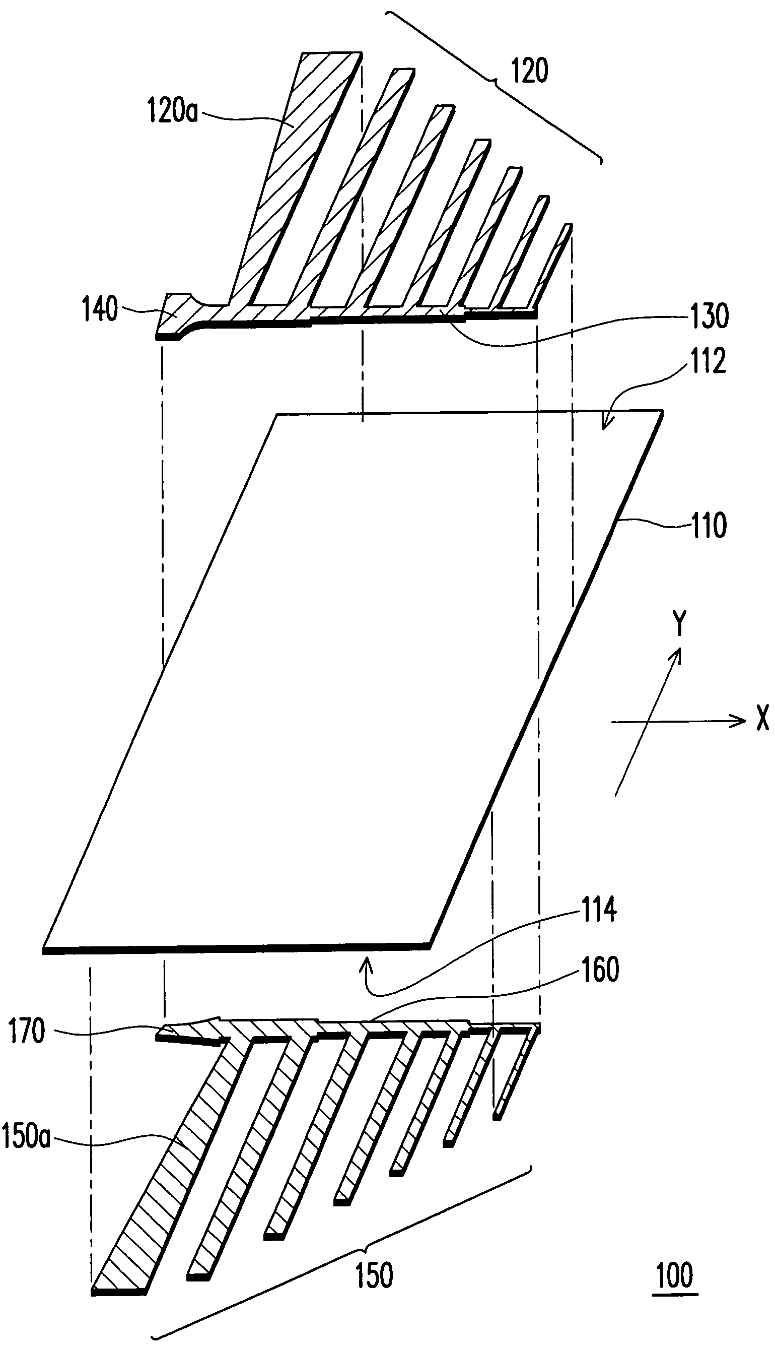
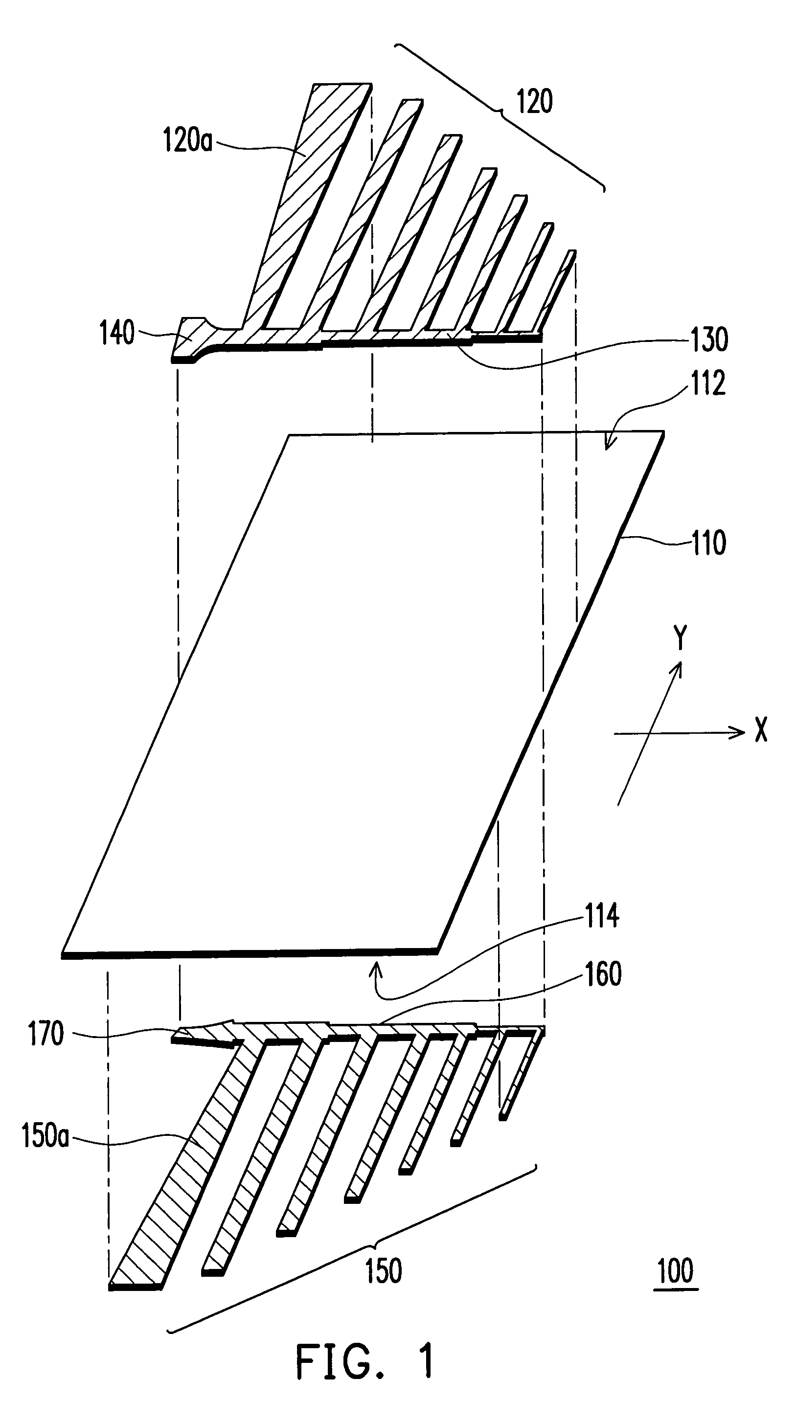
[0012]Please refer to FIG. 1, a schematic disassembly view of a log-periodic dipole array antenna according to one embodiment of the present invention. As shown in FIG. 1, the log-periodic dipole array antenna 100 includes a dielectric substrate 110, a plurality of antenna elements 120, a first symmetrical microstrip line 130, a first balun 140, a plurality of second antenna elements 150, a second symmetrical microstrip line 160, and a second balun 170. The dielectric substrate 110 has a first surface 112 and a second surface 114. The dielectric substrate 110 can be a hard substrate or other dielectric substrates commonly used in general printed circuit board, such as: a dielectric substrate composed of fiberglass or epoxy resin. The dielectric substrate 110 is used as a supporting substrate for antenna patterns, wherein the antenna patterns disposed on the first surface 112 and the second surface 114 are electrically separated by the dielectric substrate 110.

[0013]The first antenna...


PUM


Abstract

A log-periodic dipole array antenna including a dielectric substrate, and antenna elements, symmetrical microstrip lines and baluns disposed on two corresponding surfaces of the substrate is provided. The antenna elements on each surface are connected to one side of the corresponding symmetrical microstrip line, respectively. The width of at least one antenna element on each surface is broadened gradually outwards from the side of the antenna element, which is connected to the corresponding symmetrical microstrip line. In addition, the baluns are connected to the ends of the corresponding symmetrical microstrip lines, respectively. The antenna elements on one surface are in a mirror-image relation to those on the other surfaces. The log-periodic dipole array antenna features increased broadband with a thin and compact-size, better margin in design to meet different bandwidth requirements.

Description

CROSS-REFERENCE TO RELATED APPLICATION[0001]This application claims the priority benefit of Taiwan application serial no. 94124258, filed on Jul. 19, 2005. All disclosure of the Taiwan application is incorporated herein by reference.BACKGROUND OF THE INVENTION[0002]1. Field of Invention[0003]The present invention relates to an antenna, more particularly, a log-periodic dipole array antenna.[0004]2. Description of Related Art[0005]Recently, the wireless communication device has become lighter, thin, and smaller along with the evolution of integrate circuit technology. The planar antenna made by printed circuit method with advantages such as: a high level of integration and a being integrated with peripheral devices easily. The planar antenna made by printed circuit method has gradually been the main stream in current communication industry. However, the bandwidth and the radiation efficiency of the conventional antenna are unavoidably decreased after the conventional antenna being mi...

Claims


Application Information

Patent Timeline
Patent Type & Authority Patents(United States)
IPC IPC(8): H01Q11/10
CPCH01Q11/105
Inventor WANG, WEI-JENFU, JO-WANG
Owner CORETRONIC
Why Eureka
Try Eureka