Boroadband high gain probe and patch tangent laminated microstrip antenna

A microstrip antenna, high-gain technology, applied in the direction of the antenna, electrical components, radiating element structure, etc., can solve the problems of complex implementation and complex structure, and achieve the effect of novel feeding method, simple feeding structure and wide frequency band.

Active Publication Date: 2015-07-22
三亚哈尔滨工程大学南海创新发展基地
View PDF10 Cites 0 Cited by
  • Summary
  • Abstract
  • Description
  • Claims
  • Application Information

AI Technical Summary

Problems solved by technology

Its structure is relatively complex, and it is applied to the L-band
A dual-frequency high-gain coaxial feed patch antenna disclosed in the patent document with the application number 201310122359.1 uses an EBG structure to increase the antenna gain, and the implementation is relatively complicated

Method used


Image

  • Boroadband high gain probe and patch tangent laminated microstrip antenna
  • Boroadband high gain probe and patch tangent laminated microstrip antenna
  • Boroadband high gain probe and patch tangent laminated microstrip antenna

Examples


Embodiment Construction

[0029] The content of the present invention will be further described below in conjunction with the accompanying drawings, but the actual application form of the present invention is not limited to the illustrated embodiment.

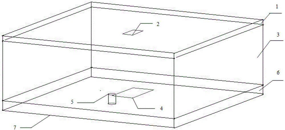
[0030] Such as figure 1 with figure 2 As shown, the broadband high-gain probe and patch tangential feeding antenna includes an upper dielectric plate 1, a parasitic patch 2, a middle dielectric plate 3, a main vibration patch 4, a feeding probe 5, a lower dielectric plate 6 and Metal ground plate7.

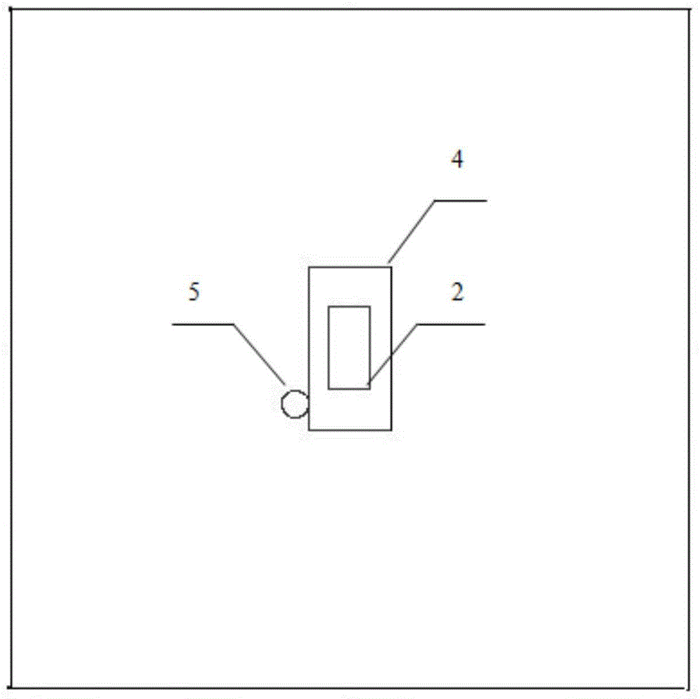
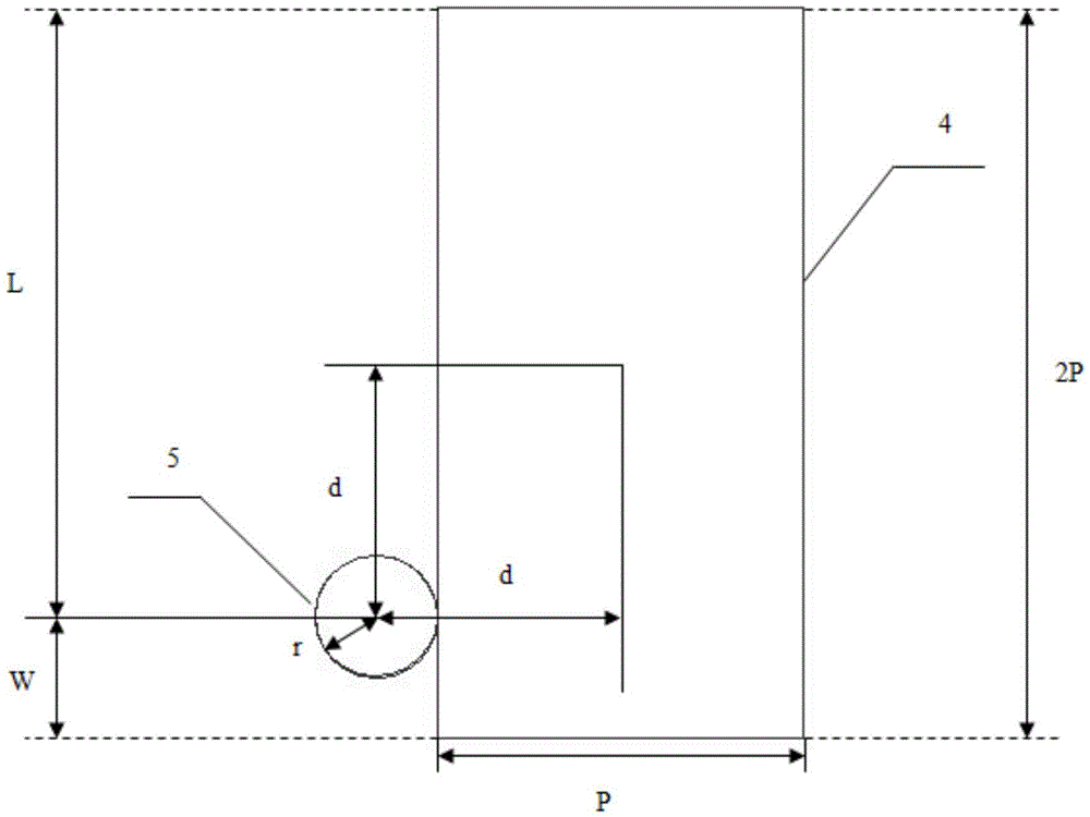
[0031] Such as image 3 As shown, the main vibrating patch 4 and the feeding probe 5 are tangent to form a tangential feeding mode between the probe and the patch, and the central axis of the feeding probe 5 and the central symmetry axis of the two sides of the main vibrating patch 4 The distances are equal and both are d; the distances L and W from the tangent point between the feeding probe 5 and the main vibration patch 4 to the two short sides of th...


PUM


Abstract

The invention provides a boroadband high gain probe and patch tangent laminated microstrip antenna. The antenna comprises a floor, a bottom dielectric layer, a probe, a main vibration patch, a middle dielectric layer, a parasitic patch and a top dielectric covering layer, wherein the three dielectric layers are sequentially overlaid; the floor is positioned below the bottom dielectric layer; the parasitic patch is positioned on the upper surface of the middle dielectric layer; the main vibration patch is positioned on the upper surface of the bottom dielectric layer; the probe is tangent with the main vibration patch to form a feeding structure; the top end of the probe and the main vibration patch are located in the same plane; the circular surface at the top end of the probe is tangent with the long side of the main vibration patch; a distance from a central shaft of the probe to a symmetry axis of the long side of the main vibration patch is equal to that from the central shaft of the feeding probe to a symmetry axis of the short side of the main vibration patch; the main vibration patch and the parasitic patch are in parallel; and symmetry axes of the main vibration patch and the parasitic patch are superposed. The antenna fully meets requirements of millimetric waveband broadband high gain wireless communication, and has the advantages of wide band, high gain, novel feeding mode, simple feeding structure, simple overall structure and the like.

Description

technical field [0001] The invention relates to a laminated microstrip antenna for wireless communication, in particular to a laminated microstrip antenna for broadband high-gain wireless communication in the millimeter wave band. Background technique [0002] Due to the development of radio communication equipment and electronic information equipment towards multi-function, miniaturization, ultra-wideband, frequency upshift, and friendly coordination with the surrounding environment, this makes broadband, miniaturization, high-gain, and millimeter-wave antennas become domestic and foreign One of the hot topics of research. It involves the broadband impedance matching technology of the antenna, the loading technology of the antenna, the reactance compensation technology of the antenna and other advanced technologies and processes. [0003] In recent years, with the vigorous development of the wireless communication industry and the increase of communication capacity, the fr...

Claims


Application Information

Patent Timeline
Patent Type & Authority Patents(China)
IPC IPC(8): H01Q1/36H01Q13/08H01Q1/38
Inventor 张昕谭世伟
Owner 三亚哈尔滨工程大学南海创新发展基地
Why Eureka
Try Eureka