Artillery Rocket Kinetic Energy Rod Warhead

a technology of kinetic energy and artillery rockets, applied in the direction of weapons, ammunition projectiles, projectiles, etc., can solve the problems of extremely violent and energetic artillery rocket payload dispense event, rods that lose velocity and effectiveness very quickly, and neither of these techniques are applicable in indirect fire artillery rockets, so as to reduce assembly costs and terminal performance, and laborious task of filling foam packs

Active Publication Date: 2007-08-28
ARMY UNITED STATES OF AMERICA AS REPRESENTED BY SEC OF THE
View PDF9 Cites 9 Cited by
  • Summary
  • Abstract
  • Description
  • Claims
  • Application Information

AI Technical Summary

Benefits of technology

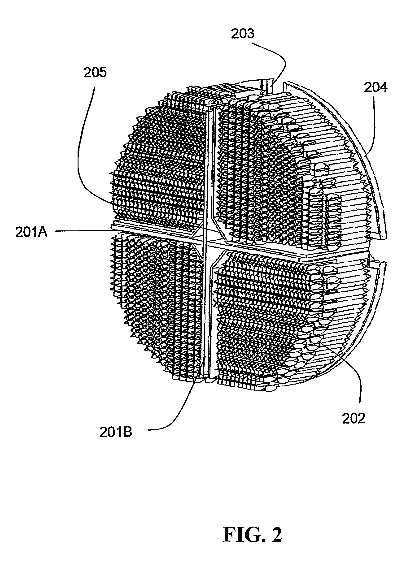
[0008]The present invention includes a novel packaging arrangement specifically designed for KE rod rocket payloads, which along with a new payload dispensing technique, yields benefits in both assembly cost and in terminal performance. Assembly costs are reduced because the laborious task of filling the foam packs with KE rod packs is eliminated. All of the KE rods are pre-assembled into wedge-shaped packs (holding trays) that are inserted as units into the rocket warhead bay.
[0009]Once the wedges of rods are in place, they are secured by a retaining band that is severed during the skin severance event. The technical performance of the warhead is improved because the tightly packed rods can be dispensed in a well-defined radial ejection event that minimizes perturbations to their angular orientation. The tightly packed rods are easily loaded to contact the flat surface of the tier pack bulkhead and are then secured together by the wraparound restraining strap. Additionally, no packing material or dunnage is used between the rods, so that dunnage fragments cannot damage the rods or disturb their orientation during dispense.
[0010]The result is a KE rod cloud that forms a predictable and repeatable expanding elliptical pattern over the target area. Holes in the rod cloud and fratricide between KE rods are thus minimized.

Problems solved by technology

The artillery rocket payload dispense event is extremely violent and energetic, since the burster must rip apart the metal warhead skin and widely disperse the payload of cluster munitions.
The rods lost velocity and effectiveness very quickly due to their low mass and random orientation dispense method.
Neither of these techniques is applicable for use in an indirect fire artillery rocket.
However, this weapon operates in a much lower velocity regime than a supersonic artillery rocket; thus, its payload dispensing system is not applicable to the present invention.
No currently utilized munition packaging techniques are appropriate for use with artillery rocket KE rod payloads.
If the rods are placed directly into the rocket warhead bay, they are dispensed in random orientations and quickly lose their velocity and lethality due to air drag.
Installing them into foam packs and then installing the foam packs one at a time into the rocket is labor intensive.
Additionally, the explosive forces needed to break up the foam packs and expel the rods from the rocket would cause many rods to be damaged during dispense.
Further, many rods would be dispensed in random with ineffective orientations.
Thus, the effectiveness of the warhead payload would be severely degraded.

Method used


Image

  • Artillery Rocket Kinetic Energy Rod Warhead
  • Artillery Rocket Kinetic Energy Rod Warhead
  • Artillery Rocket Kinetic Energy Rod Warhead

Examples


Embodiment Construction

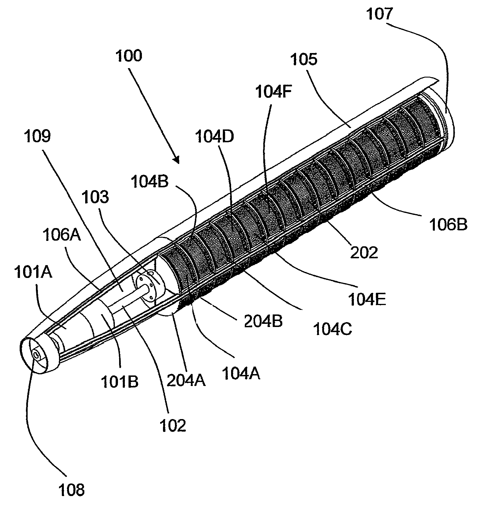
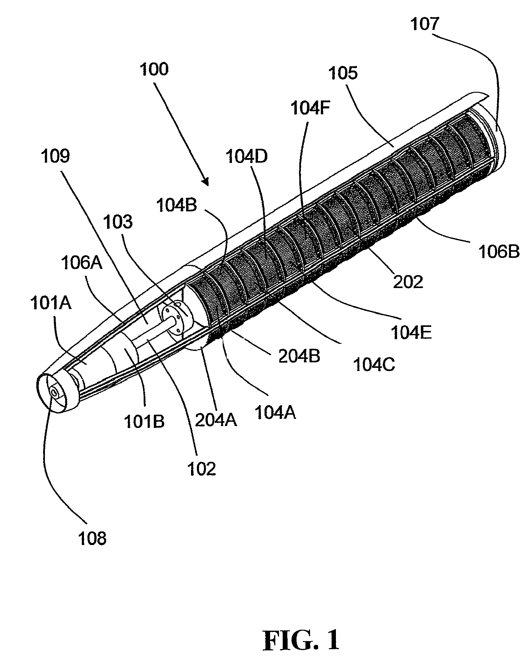
[0015]In FIG. 1, in warhead 100 the KE rods 202 are visible in that the straps and donnage over the KE rod packs or tier packs 104 have been removed. The forward portion of the warhead bay 109 contains ballast weights 101A and 101B that tailor the mass, center of mass location and inertia properties of the rocket. The ballast weights are designed to ensure that the overall mass and inertia properties of the KE rod payload matches the prior art cluster munition payload, so that no changes will be required in the prior art trajectory simulations and firing tables. A rocket center column 102 runs down the center of the warhead bay. The rocket center column 102 serves as the attachment point for the ballast weights 101A, 101B, the warhead bay bulkhead collar 103, and the stages of tier packs 104A, 104B, 104C, 104D 104E, 104F, etc. Tier pack 104A is situated between bulkhead 204A and Bulkhead 204B. The KE rods or flechettes 202 are tightly nested together in a multiplicity of tier packs ...


PUM


Abstract

A KE rod warhead for artillery rockets contains a multiplicity of KE rod penetrators housed in trays and packaged into bays or tier packs that are stacked and positioned around a center column of the warhead. The warhead has a skin which is severed upon the rocket entering a target area. The KE rods are situated and housed in such a manner that upon release the rods experience a minimum of pitching or tumbling upon entering the air stream giving the rods an optimal lethality against a designated target. The KE rod artillery rocket contains no explosive munitions, so it can be used without civilian and environmental concerns over unexploded ordnance.

Description

DEDICATORY CLAUSE[0001]The invention described herein may be manufactured, used and licensed by or for the Government for U.S. governmental purposes, provisions of 15 U.S.C. section 3710c apply.BACKGROUND OF THE INVENTION[0002]The prior art for artillery rocket lethal warhead packaging includes unitary high explosive bombs, autonomous or semi-autonomous submunitions designed to attack armor, and anti-personnel payloads comprised of hundreds of fragmenting, explosive filled cluster munition bomblets. In order to construct the cluster munition warheads, cylindrical cluster munitions are installed into longitudinal holes in large cylindrical foam overpacks. Multiplicities of overpacks are installed into longitudinal holes in large cylindrical foam overpacks.[0003]The rocket dispenses its payload by means of an explosive bursting charge in the warhead bay that splits the warhead skin along pre-scored longitudinal lines, disintegrating the cylindrical foam overpacks and scattering the cl...

Claims


Application Information

Patent Timeline
Patent Type & Authority Patents(United States)
IPC IPC(8): F42B12/60
CPCF42B12/60F42B12/64
Inventor BITTLE, DAVID AJIMMERSON, GARY TCOTHRAN, JULIAN LBLAISE, DONALD H
Owner ARMY UNITED STATES OF AMERICA AS REPRESENTED BY SEC OF THE
Why Eureka
Try Eureka