Heat pipe excellent in reflux characteristic

a heat pipe and reflux characteristic technology, applied in the field of heat pipes, can solve the problems of large flow resistance, small flow cross-sectional area of flow path, and inability to cool a personal computer, server, or portable electronics device, etc., and achieve the effect of improving heat transporting capacity and promoting reflux

Active Publication Date: 2007-08-28
THE FUJIKURA CABLE WORKS LTD +1
View PDF33 Cites 14 Cited by
  • Summary
  • Abstract
  • Description
  • Claims
  • Application Information

AI Technical Summary

Benefits of technology

[0011]The present invention has been conceived in view of the aforementioned technical problems and its object is to provide a heat pipe which can further improve a heat transporting capacity by promoting reflux of a liquid phase working fluid of a heat pipe wherein a porous body is employed as a wick.
[0013]According to the heat pipe of the present invention, therefore, flow of the condensable, liquid phase working fluid toward the evaporating part takes place not only in the cavity of the porous body but also in the direct reflux flow passage in the porous body, and the flow cross-sectional area of the direct reflux flow passage is large, and the flow resistance is small in comparison with that of the porous body. Accordingly, the reflux of the liquid phase working fluid to the evaporating part is promoted and the amount of the evaporation of the working fluid at the evaporating part is increased, thereby increasing the heat transport of the heat pipe as a whole. Also, since the direct reflux flow passage functions as a reservoir portion for reserving the liquid phase working fluid, the amount of the working fluid contained in the evaporating part or in its vicinity is increased. As a result, shortage of condensable, liquid phase working fluid will not occur even when the inputted amount of heat is increased, and drying out is thereby prevented or suppressed in advance.
[0015]In this case, the direct reflux flow passage which contributes to the reflux of the liquid phase working fluid is arranged by connecting a plurality of portions of condensing part side to the evaporating part, so that the liquid phase working fluid refluxes from a plurality of portions of the condensing part side to the evaporating part, and is reserved in sufficient amount in the evaporating part where the heat is inputted from outside or in the vicinity of the evaporating part. Accordingly, a disadvantage such as drying out caused by an increase in the inputted amount of heat is prevented or suppressed in advance.
[0016]Moreover, according to the present invention, it is possible to construct the direct reflux flow passage of a thin slit, or thin slits, formed on the surface of the porous body.
[0018]In this case, the direct reflux flow passage may be formed into the thin slit, or the thin slits, or into a through passage, or through passages, between the inner face of the container and the porous body. Accordingly, the liquid phase working fluid refluxes to the evaporating part through the direct reflux flow passage, so that the flowage is smoothened and reflux rate is thereby increased. Therefore, the heat transporting capacity of the heat pipe as a whole is improved.

Problems solved by technology

At the same time, how to cool a personal computer, a server, or a portable electronics device, which are enhanced in its compactness and capacity, has been becoming a problem in recent days.
If the liquid phase working fluid is refluxed by utilizing the pumping force of the capillary pressure, the liquid phase working fluid is carried inside of the wick; however, in case of the wick of a porous body, because a flow path created therein is the cavity created among the fine powders as the material of a porous body, so that the flow cross-sectional area of the flow path has to be small and as intricate as a maze.
Therefore, there is a disadvantage in that the flow resistance is relatively big.
Also, the liquid phase working fluid is to be contained in the cavity so that an amount of the working fluid is not always sufficient.
Accordingly, if the inputted amount of heat from outside increases suddenly and drastically, for example, there will be a possibility of so-called drying out such that the wick goes into a dry state due to a shortage of the liquid phase working fluid fed to the portion where the evaporation of the working fluid takes place.

Method used


Image

  • Heat pipe excellent in reflux characteristic
  • Heat pipe excellent in reflux characteristic
  • Heat pipe excellent in reflux characteristic

Examples


Embodiment Construction

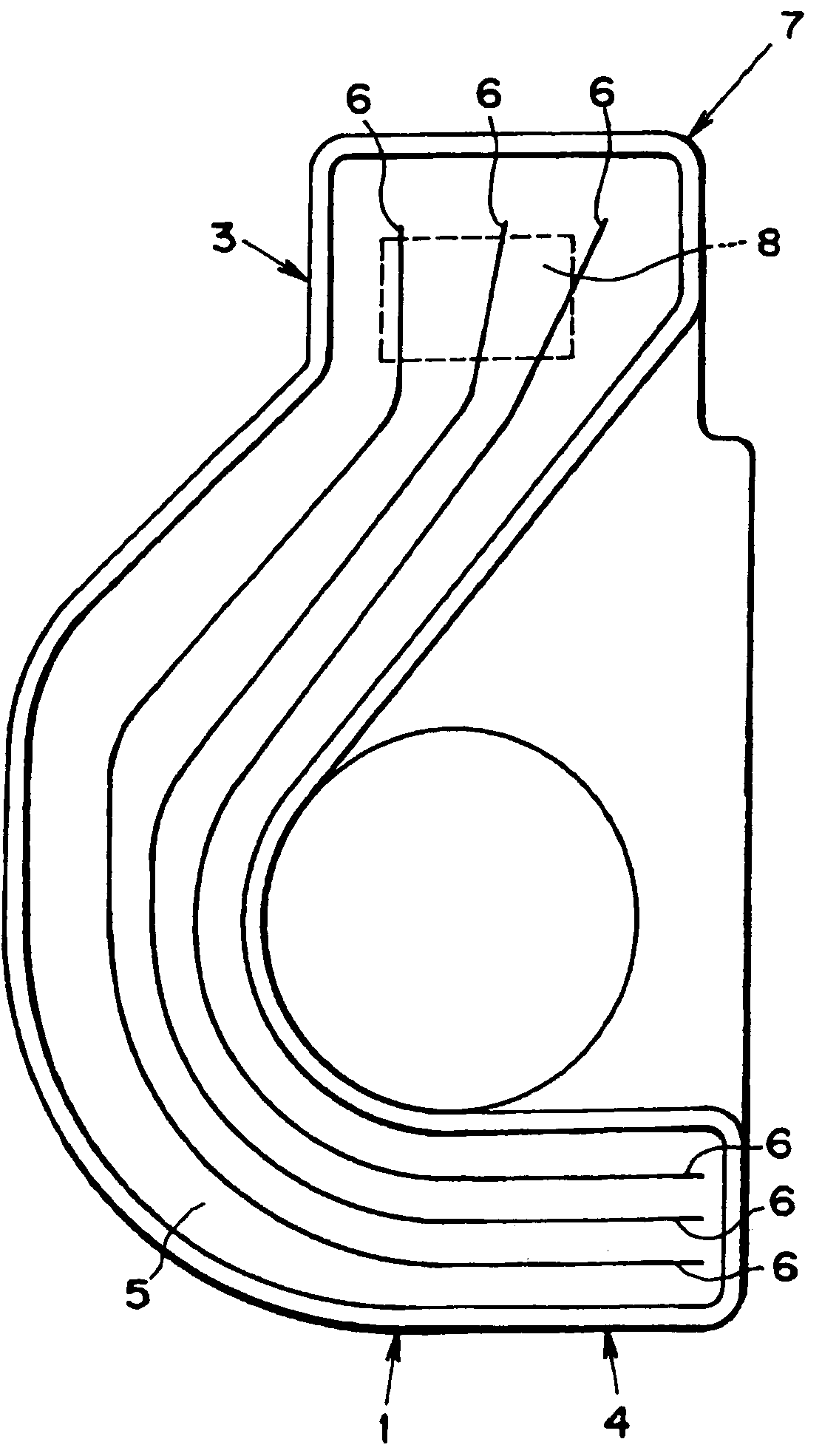
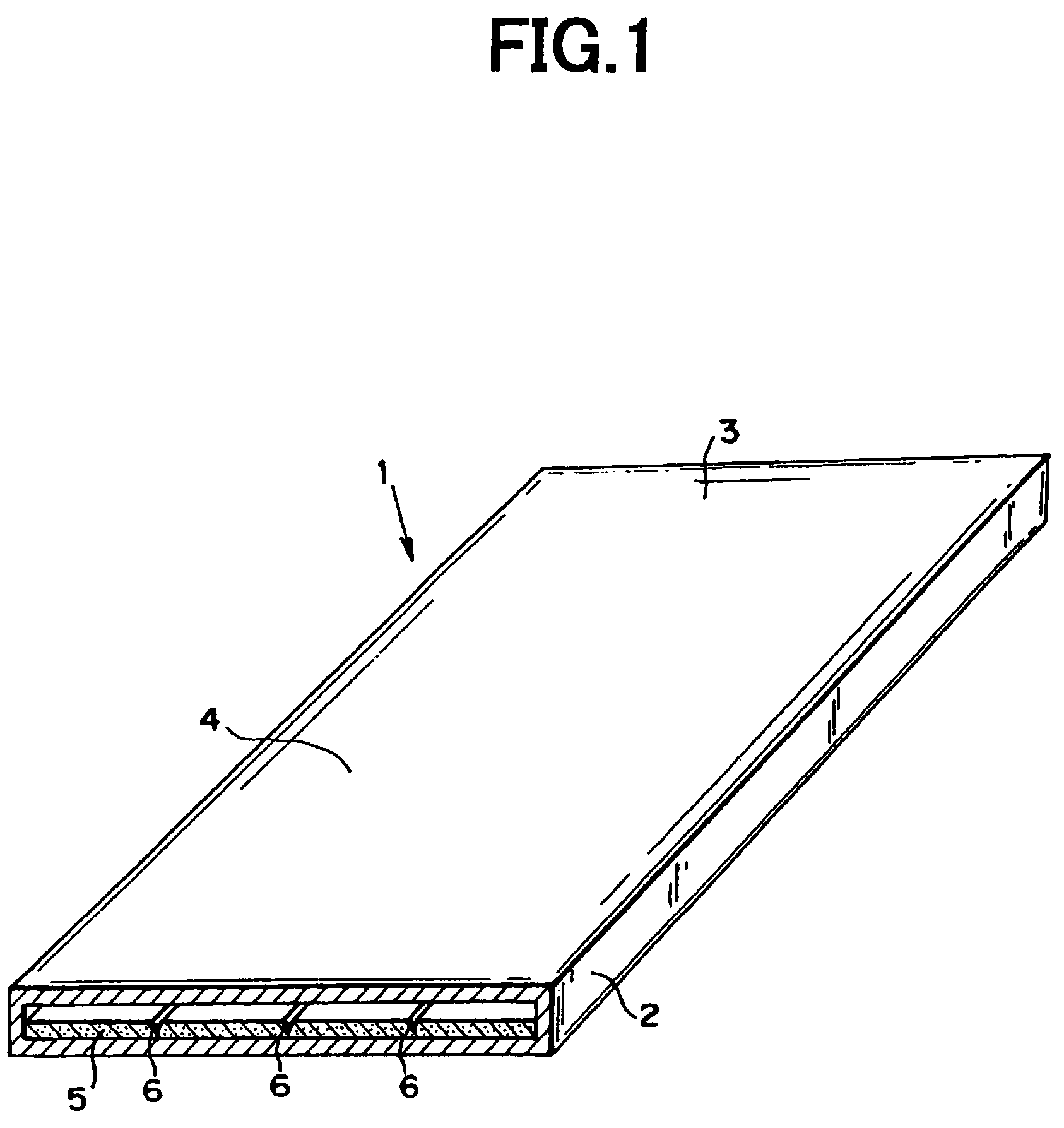
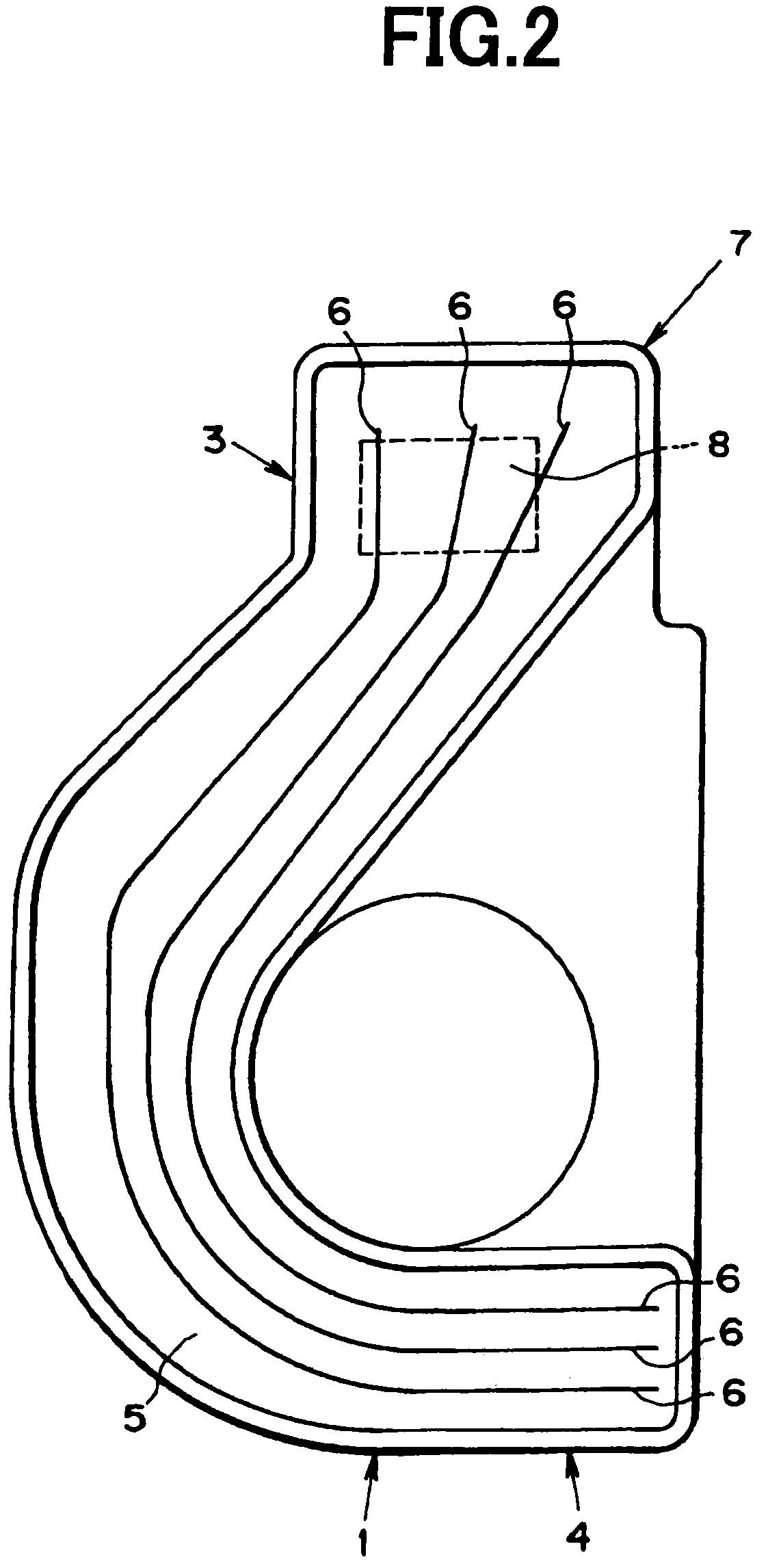
[0027]Here will be described the specific embodiments of the present invention with reference to the accompanying drawings. FIG. 1 shows one example of the heat pipe (or the vapor chamber) according to the present invention, and the heat pipe shown therein is constructed to be the flat thin-shaped type. Namely, a container 2 of the flat thin-shaped type heat pipe 1 is constructed to have a flat thin-shaped cross section. The inside of the container 2 is vacuum de-aerated and a condensable, liquid phase working fluid such as pure water, alcohol or the like is encapsulated therein. Here, for example, the encapsulating amount of the working fluid may be governed by: (Volume of wick×porosity+predetermined value α). One of the end portions of the flat thin-shaped type heat pipe 1 thus constructed is an evaporating part 3, and another end portion is a condensing part 4.

[0028]A wick 5 is arranged on the bottom face of the container 2. This wick 5 is a porous sintered compact, and its mater...


PUM


Abstract

A heat pipe wherein a condensable liquid phase working fluid is encapsulated in a container sealed in air-tight condition; wherein the wick composed of the porous body for refluxing the liquid phase working fluid by a capillary pressure is provided in the container; wherein a part of the container functions as an evaporating part for evaporating the working fluid by means of inputting the heat from outside; and wherein another part of the container functions as a condensing part for condensing a vapor of the working fluid by means of radiating the heat to the outside; comprises a direct reflux flow passage for flowing the liquid phase working fluid to the evaporating part, which has a flow cross-sectional area greater than that of a cavity formed in the porous body.

Description

BACKGROUND OF THE INVENTION[0001]1. Field of the Invention[0002]The present invention relates to a heat pipe for transporting heat as latent heat of a working fluid such as a condensable fluid, and especially to a heat pipe which is constructed to create a so-called pumping force for refluxing a liquid phase working fluid to a portion where it evaporates, by means of a capillary pressure of a porous material.[0003]The present invention relates to the subject matter contained in Japanese Patent Application No.2003-38404, filed on Feb. 17, 2003, which is expressly incorporated herein by reference.[0004]2. Related Art[0005]In the customary way, a heat pipe for transporting heat in the form of latent heat of a working fluid is well known in the prior art. The heat pipe of this kind is a heat conducting element encapsulating a condensable fluid such as water in a sealed receptacle (container) after evacuating an air therefrom, and which is constructed to transport the heat as latent heat...

Claims


Application Information

Patent Timeline
Patent Type & Authority Patents(United States)
IPC IPC(8): F28D15/00H05K7/20F28D15/02F28D15/04
CPCF28D15/0233F28D15/046
Inventor KAWAHARA, YOUJIMOCHIZUKI, MASATAKAMASHIKO, KOICHIKIYOOKA, FUMITOSHIAGATA, HIROAKI
Owner THE FUJIKURA CABLE WORKS LTD
Why Eureka
Try Eureka