Electrical connector

a technology of electrical connectors and connectors, applied in the direction of coupling device connections, coupling protective earth/shielding arrangements, two-part coupling devices, etc., to achieve the effect of simplifying fabrication processes and facilitating fabrication

Inactive Publication Date: 2007-08-28
LONGWELL
View PDF6 Cites 5 Cited by
  • Summary
  • Abstract
  • Description
  • Claims
  • Application Information

AI Technical Summary

Benefits of technology

[0006]For solving the foregoing problems, one object of this invention is to provide an e

Problems solved by technology

However, the plurality of terminal structures make the whole grounding structure too wide and thin, and lead the middle portion of the grounding structure into bend, and to cause the sinking phenomenon occurs in the middle portion of the grounding structure.
An improve method

Method used


Image

  • Electrical connector
  • Electrical connector
  • Electrical connector

Examples


Embodiment Construction

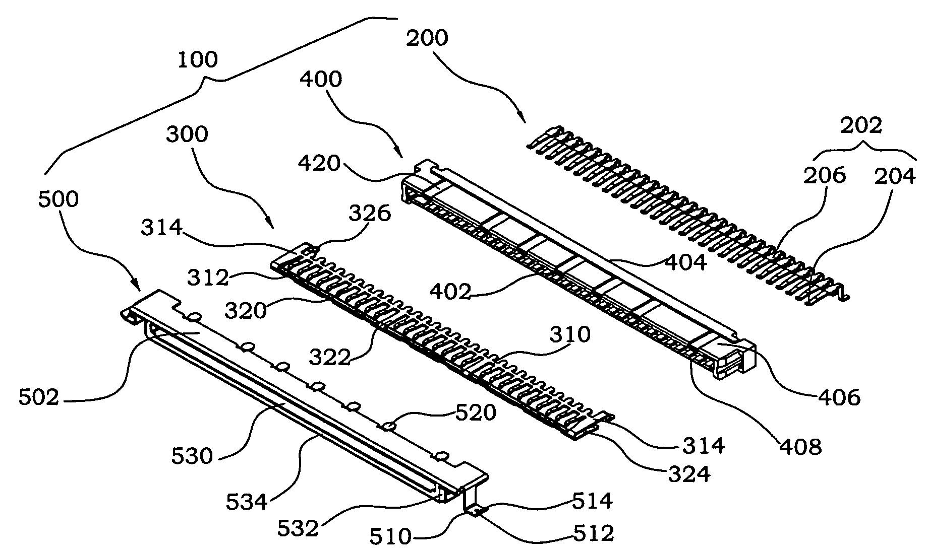
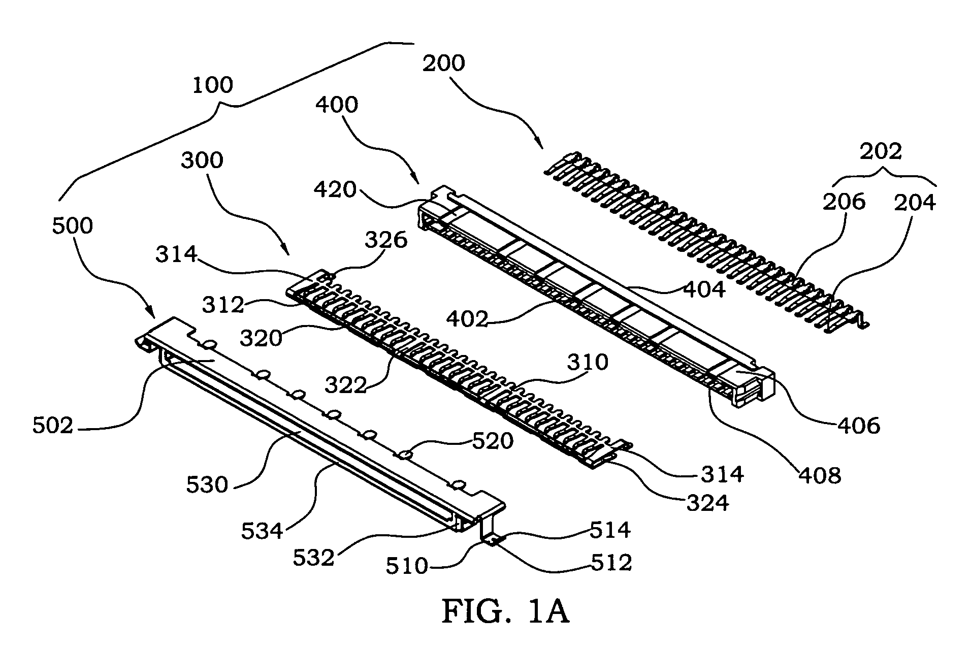
[0033]FIG. 1A is a disassembling structure diagram illustrating an electrical connector in accordance with one embodiment of present invention. As shown in FIG. 1A, an electrical connector 100 includes a terminal component 200, a grounding component 300, an insulating housing 400 and a metal shell 500. The terminal component 200 includes a plurality of terminals 202 made by punching a metal piece and the terminals 202 are applied to as signal terminals. In the present embodiment, every terminal 202 includes a contacting portion 204 and a wedging portion 206, wherein the contacting portion 204 is used to contact with a terminal of a male connector (not shown in FIG. 1A) and the wedging portion 206 is used to help the terminal component 200 wedged in the insulating housing 400. As shown in FIG. 1A, the grounding component 300 includes a main axis 310, a folding piece 312, two side arms 314 and a plurality of cantilevers 320, wherein two ends of the main axis 310 and two ends of the fo...


PUM


Abstract

An electrical connector includes: a terminal element; a grounding element; an insulating housing; a metal shell enclosing the insulating housing; and two solder terminals extended outward from the metal shell. Wherein the grounding element has at least a supporting rib which is utilized to enhance the structure strength of the grounding element so as to ensure a good grounding effect in limited space. Besides, every one of those solder terminals of the metal shell has a winding portion bended in a tilting angle. Additionally, the metal shell further includes a partner-fitting portion, and two short sides of the peripheral thereof bended backward to form a chamfer-type guiding portion so as to make a corresponding connector connect to the electrical connector smoothly.

Description

BACKGROUND OF THE INVENTION[0001]1. Field of the Invention[0002]The present invention relates to a connector, and more especially, to an electrical connector with good grounding effect.[0003]2. Background of the Related Art[0004]Electrical connector is widely applied in the electrical apparatus, such as the notebook, the mobile phone and the fax. The electrical connector combining with a male connector is electrically connected to a printed circuit board (PCB) of a host, to provide the electrical connection between two electrical apparatus.[0005]In general, the electrical connector includes an insulating housing, a plurality of grounding terminals and signal terminals which are arranged in the insulating housing separately and parallelly, and a cover shell holding on the insulating housing, wherein the grounding terminals contact with the cover shell to provide the grounding effect. The usual grounding terminals are made by punching a metal piece to form a plurality of terminal stru...

Claims


Application Information

Patent Timeline
IPC IPC(8): H01R13/648H01R12/71H01R12/77H01R24/00H01R24/60
CPCH01R12/724H01R13/65802H01R13/6582
Inventor TSENG, TIEN-CHIH
Owner LONGWELL
Why Eureka
Try Eureka