Standing-wave electron linear accelerator

a linear accelerator and standing wave technology, applied in the field of particle acceleration, can solve the problems of low efficiency of a traveling wave accelerator, small adjustment range, and travel wave accelerator, and achieve the effect of enabling high intensities

Inactive Publication Date: 2007-08-28
SCANTECHIBS IP HLDG
View PDF11 Cites 10 Cited by
  • Summary
  • Abstract
  • Description
  • Claims
  • Application Information

AI Technical Summary

Benefits of technology

[0010]Advantageously, the particle accelerator system includes a bunching section and an accelerating section that are directly coupled via a common wall. A first passageway formed in the common wall shared between the accelerating and bunching sections enables charged particles to travel between the two sections without significant energy dispersion. A second passageway formed in the common wall shared between the accelerating and bunching sections enables electromagnetic power to propagate from the accelerating section into the bunching section.

Problems solved by technology

Unfortunately, traveling wave accelerators have several disadvantages.
First, the efficiency of a traveling wave accelerator is low, as the resulting particle beam contains particles that are not tightly bunched together.
Second, the operating parameters of the traveling wave accelerators are fixed and there is little range for adjustment.
Third, traditional traveling wave accelerators are not capable of producing particle beams at high intensities.
However, this structure alone is inefficient for capturing a large number of particles to bunch and form into a beam.
Unfortunately, the presence of the drift space creates several disadvantages.
Second, a larger degree of energy dispersion occurs much more at higher intensities than at lower intensities.
At very high intensities, the degree of the dispersion is so large that the linear electron accelerator cannot produce any bunches of particles in the resulting beam, which renders the linear accelerator useless at very high intensities.
Thus, the large degree of dispersion at high intensities limits the possible applications for the linear accelerator.
Changes in temperature or poor connections, among other factors, can cause the radio-frequency generators to become out of phase, which in turn causes instability in the accelerator system.

Method used


Image

  • Standing-wave electron linear accelerator
  • Standing-wave electron linear accelerator
  • Standing-wave electron linear accelerator

Examples


Embodiment Construction

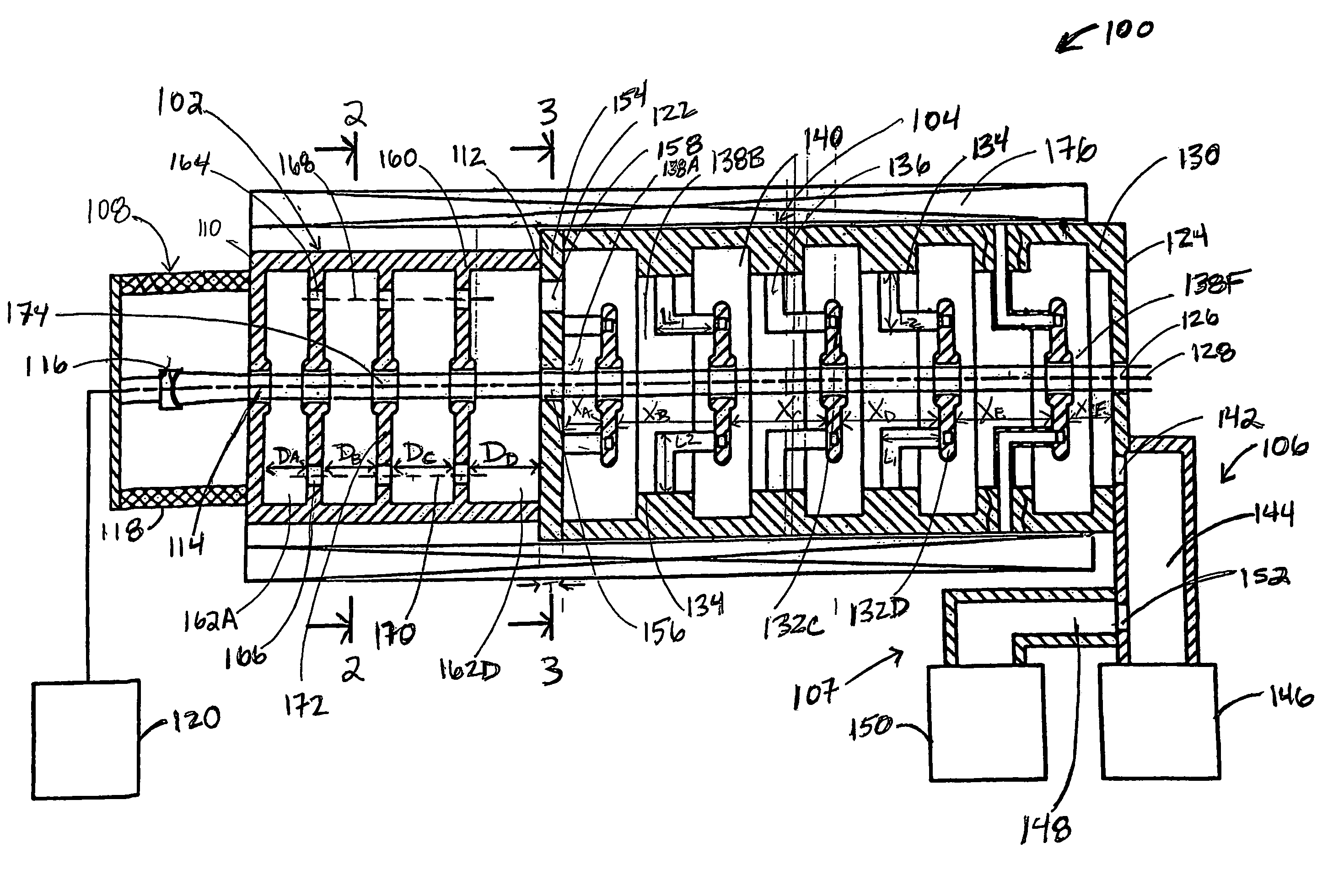
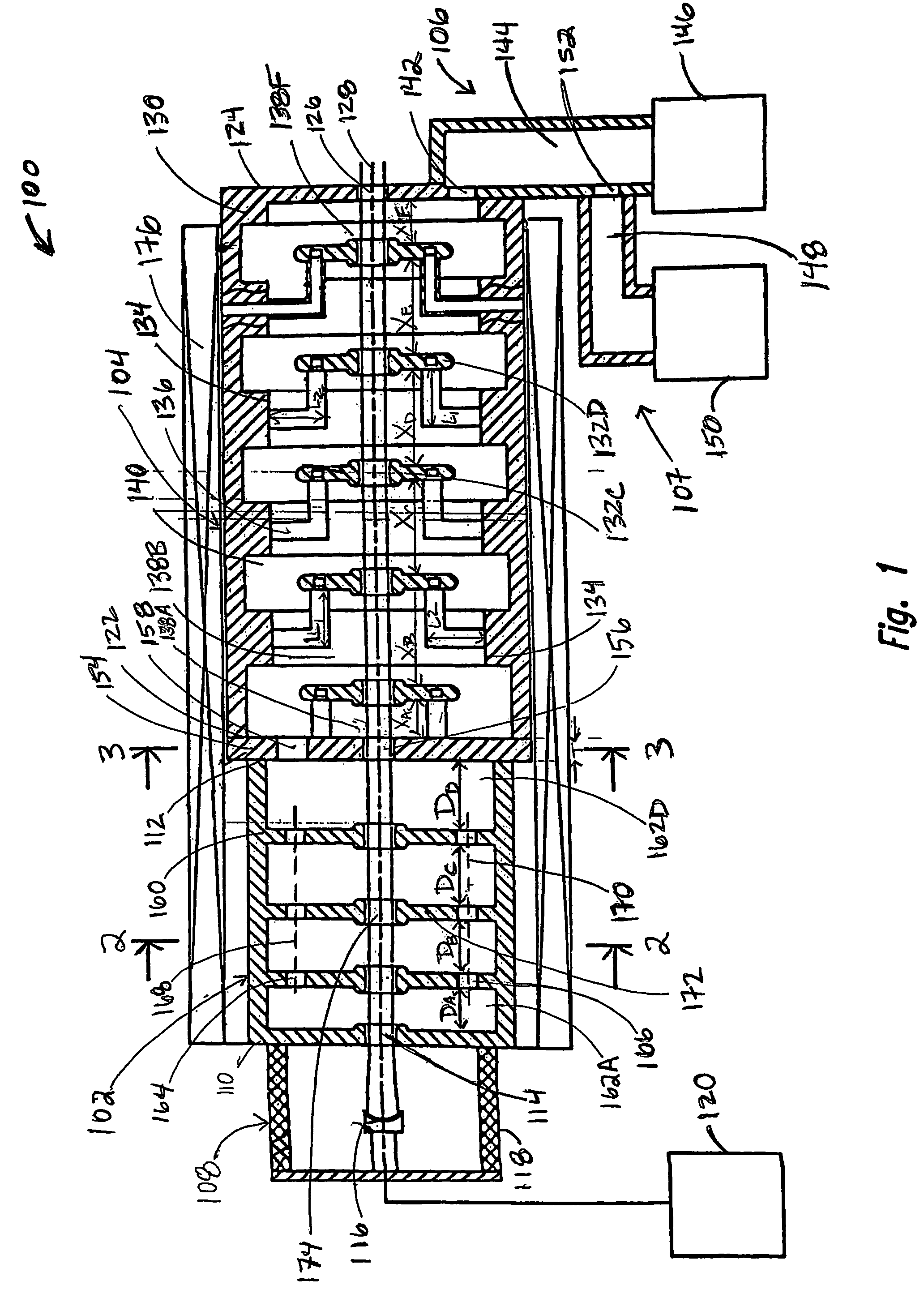
[0022]Referring now to the drawings in which like numerals represent like elements or steps throughout the several views, FIG. 1 displays a pictorial sectional view of a particle accelerator system 100 according to a first embodiment of the present invention. Particle accelerator system 100 includes a bunching section 102, an accelerating section 104, an electromagnetic drive subsystem 106, a vacuum subsystem 107, and an injector 108. Preferably, the bunching section 102 and the accelerating section 104 comprise standing-wave sections 102, 104 which are operable to accelerate charged particles through the transfer of energy from electromagnetic power provided by the electromagnetic drive subsystem 106.

[0023]The bunching section 102 has a first end 110 and a second end 112. The injector 108 is positioned proximate the first end 110 of the bunching section 102 and is connected to an input port 114 of the bunching section 102. Preferably, the injector 108 comprises an electron injector...


PUM

PropertyMeasurementUnit
frequencyaaaaaaaaaa
currentaaaaaaaaaa
radio-frequency poweraaaaaaaaaa

Abstract

A particle accelerator system, including apparatuses and methods, for producing a beam of bunched charged particles at high intensities and with minimal energy dispersion comprises a bunching section having a plurality of bunching cavities, an accelerating section having a plurality of accelerating and coupling cavities, and an electromagnetic drive subsystem having a single radio-frequency (RF) generator coupled to the accelerating section at a single location. The accelerating and bunching sections are directly coupled and share a common wall, which may have a resonant coupling cavity therein, such that charged particles bunch in the bunching section and travel through the common wall into the accelerating section where they are accelerated and exit the particle accelerator system as a beam of bunched charged particles. Preferably, a phase shift of one hundred-eighty degrees (180°) (or it radians) is created between the electric fields of successive bunching cavities in the bunching section.

Description

CROSS REFERENCE TO RELATED APPLICATION[0001]This application claims the benefit of priority to U.S. provisional application Ser. No. 60 / 418,198, which is entitled “Electron Standing-Wave Linear Accelerator” and was filed on Oct. 11, 2002.FIELD OF THE INVENTION[0002]The invention relates, generally, to the field of particle acceleration and, more specifically, to standing-wave linear accelerators having high-intensity electron beams.BACKGROUND OF THE INVENTION[0003]Particle accelerators produce high-speed, high-energy beams of particles that are utilized in a variety of applications, including radiation therapy, defense technology, imaging, and materials testing. A form of such particle accelerators, electron linear accelerators, are utilized for the sterilization of medical devices and food irradiation.[0004]Traditionally, traveling wave accelerators have been used to achieve the goals of particle acceleration. Unfortunately, traveling wave accelerators have several disadvantages. F...

Claims


Application Information

Patent Timeline
Patent Type & Authority Patents(United States)
IPC IPC(8): H05H9/00C12MH05H9/04
CPCH05H9/04
Inventor PIROZHENKO, VITALY M.BOWSER, GARY F.BELUGIN, VLADIMIR M.ROZANOV, NIKOLAY E.
Owner SCANTECHIBS IP HLDG
Why Eureka
Try Eureka