Cardiac tissue energy dispersion device

a tissue energy dispersion and energy dispersion technology, applied in the field of tissue energy dispersion devices, can solve the problems of weakened or ineffective cardiac muscles, affecting the electrical conduction and overall mechanical performance of the heart, and affecting the cardiac pumping function, so as to achieve the effect of enhancing cardiac outpu

Inactive Publication Date: 2007-10-11
ROYALTY JOHN W +1
View PDF5 Cites 9 Cited by
  • Summary
  • Abstract
  • Description
  • Claims
  • Application Information

AI Technical Summary

Benefits of technology

[0010] It is an aspect of the present invention to provide an electromagnetic biventricular assist device to augment cardiac output in a safe manner, without injury to the heart or surrounding tissues.
[0012] In an embodiment of the invention, an electromagnetic cardiac assembly for assisting ventricular output in a human heart is provided. The electromagnetic cardiac assembly includes a magnetic mat adapted for mounting inside a human body near the heart. The mat includes a material responsive to application of an electromagnetic field so as to be movable in a first direction into compressive relation with the heart in response to application of the electromagnetic field and movable in a second direction out of the compressive relation to permit the heart to relax when application of the electromagnetic field is discontinued. The electromagnetic cardiac assembly also includes an electromagnetic subassembly adapted for mounting on the human body in functionally cooperative relation with respect to the mat, and for alternately generating and discontinuing the electromagnetic field so that the mat alternately moves into and out of the compressive relation with the heart. The electromagnetic cardiac assembly also includes an energy dispersion device adapted for mounting between the mat and the heart. The energy dispersion device is constructed and arranged to disperse energy between the magnetic mat and the heart. The electromagnetic cardiac assembly further includes a pressure transducer for measuring intra-cardiac pressure within the heart and for generating a signal as a function of the intra-cardiac pressure, and a control circuit for receiving the signal generated by the transducer and for controlling an intensity of the electromagnetic field generated by the electromagnetic subassembly as a function of the signal to thereby control a degree to which the mat compresses the heart as a function of the intra-cardiac pressure within the heart.

Problems solved by technology

During the aging process, weakened or ineffective cardiac muscles may inhibit the cardiac pumping function from either the right, left, or both ventricles.
When the pumping activity of the heart cannot meet the body's demands, systemic shock and subsequent organ dysfunction (such as pulmonary edema and renal failure) can result.
Weakened heart muscles can also result in an over-distended, dilated myocardium, which may have a detrimental effect on the electrical conduction and overall mechanical performance of the heart.
However, heart transplants are difficult to obtain since there is a limited donor supply.
Moreover, artificial hearts have proved not entirely effective in duplicating cardiac contractions, are extremely expensive, and are known to be rejected by the human body.
It can be appreciated that the device is quite cumbersome, difficult to implant, and has achieved little, if any, acceptance. FIG. 4 of the '617 patent illustrates an alternate arrangement in which a compressor element is provided posteriorly to the heart and is movable to compress the heart against the rib cage.
This embodiment is somewhat more practical, but nevertheless problematic in a number of respects.
For example, no means are provided for evaluating the amount of compressive resistance or intra-cardiac pressure of the heart during compression thereof.
As a result, the compressor element may either apply insufficient compressive force to the heart, thereby resulting in ineffective ventricular assist, or apply excessive compressive force, thereby damaging the heart.
Additionally, providing a compressor element posteriorly to the heart requires complex surgery in which the entire chest cavity must be opened.
Moreover, such placement of the compressor element is largely impractical since the aorta, esophagus and spine are all disposed in close proximity to the posterior portion of the heart, and leave little room for insertion of any type of assist device.
Although the device includes a transducer and control circuit to regulate the compressive force that is applied to the heart, direct cardiac compression, while attempting to augment cardiac output in the failing heart, may result in trauma to the epicardium and potentially to the myocardium.

Method used


Image

  • Cardiac tissue energy dispersion device
  • Cardiac tissue energy dispersion device
  • Cardiac tissue energy dispersion device

Examples


Embodiment Construction

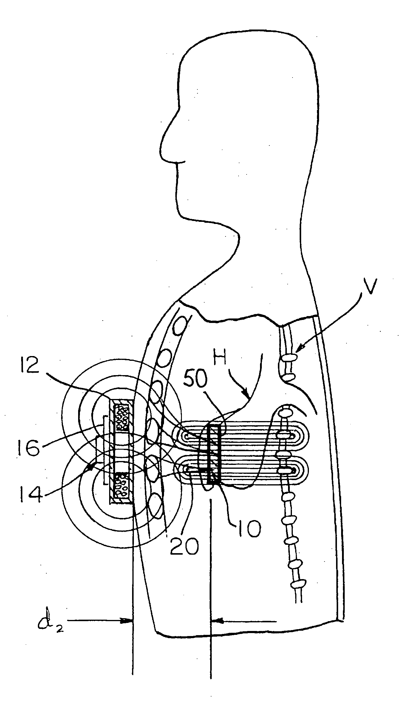
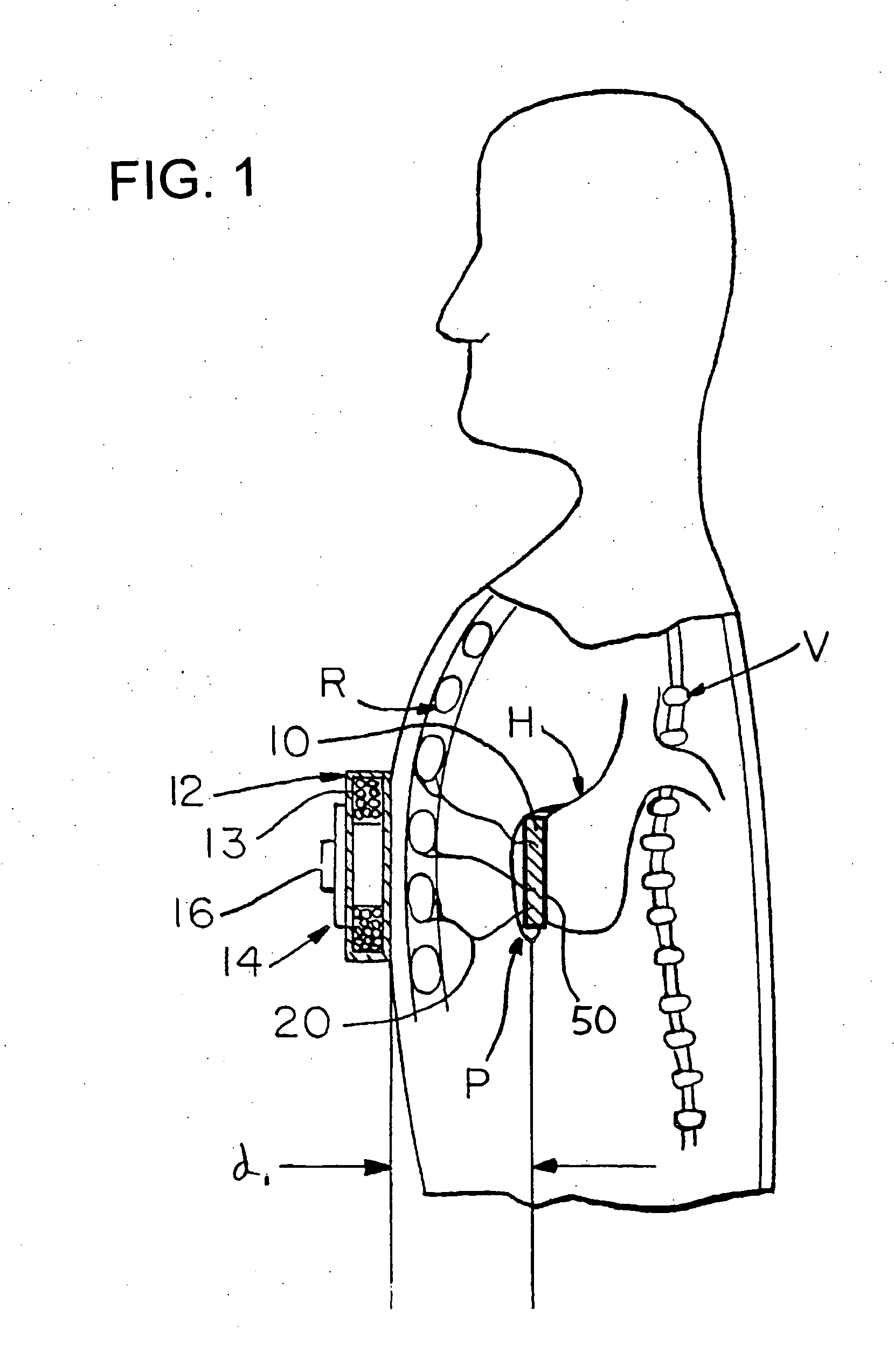
[0020]FIG. 1 is a side sectional view taken through the human body and the cardiac assist device of the present invention, which is shown in non-compressive relation with the human heart.

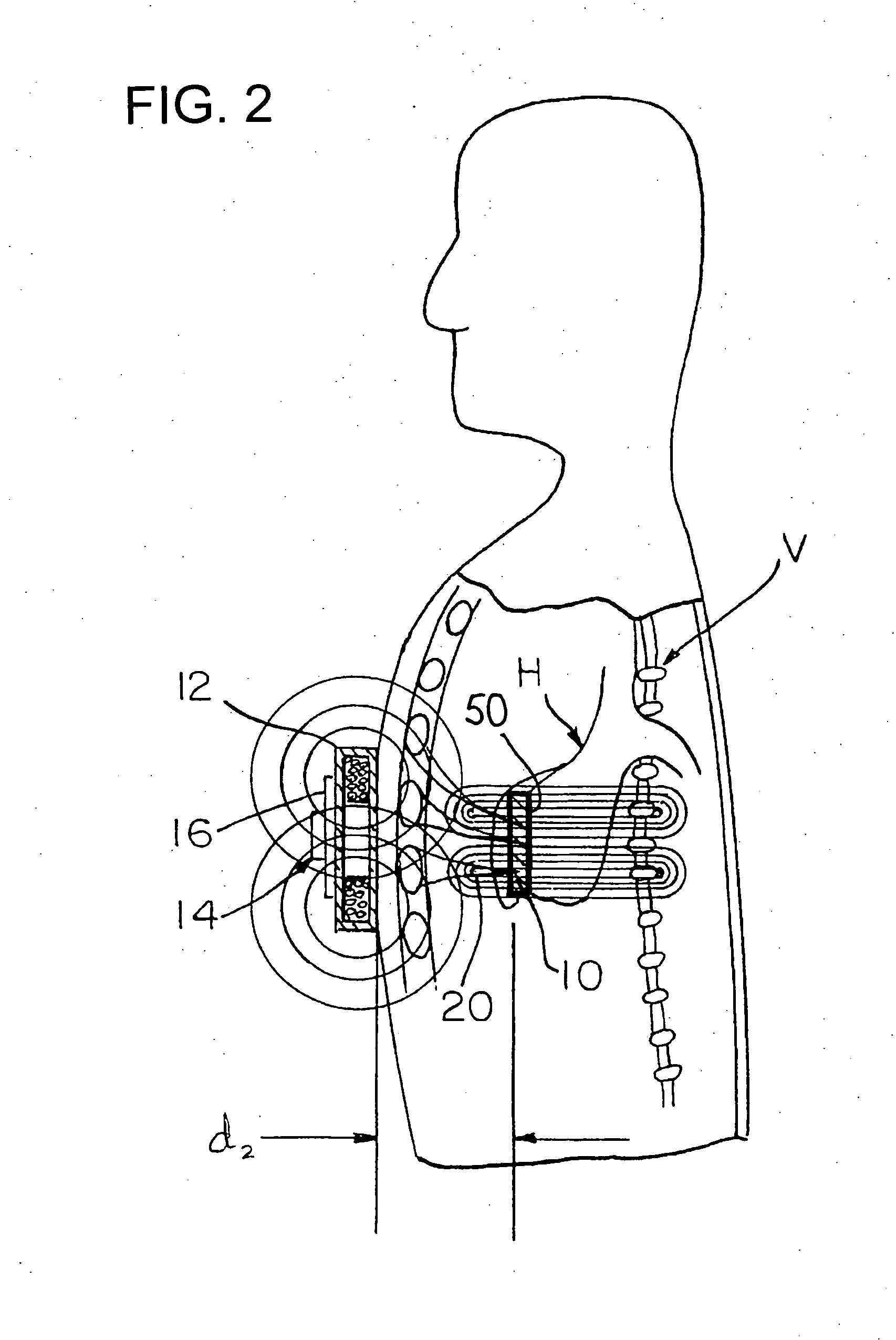
[0021] In the illustrated embodiment, the device includes a magnetic mat 10 which is adapted to be mounted inside the human body inside of the rib cage R, near the heart H. Preferably, the mat 10 is a permanent magnet made from a flexible ferro-magnetic material, including but not limited to samarium cobalt, neodymium iron, and neodymium iron boron (NeFeBo). It can be appreciated, however, that the mat 10 may comprise other materials (such as a superconductive material) so long as the mat 10 is sufficiently responsive to application of an electromagnetic field to compress the heart in accordance with the principles of the present invention. Regardless of the material used, however, the exterior surface of the mat should be chemically inert, and not immunogenic, so that it does not react with blood,...


PUM


Abstract

An electromagnetic cardiac assembly adapted to assist ventricular output in a human heart includes a magnetic mat adapted for mounting inside a human body near the heart. The mat is made from a material responsive to application of an electromagnetic field so as to be movable into compressive relation with the heart in response to application of the electromagnetic field thereto and movable out of said compressive relation to permit the heart to relax when application of the electromagnetic field is discontinued. The assembly also includes an electromagnetic subassembly adapted for mounting on the human body in functionally cooperative relation with respect to the mat, and an energy dispersion device adapted for mounting between the mat and the heart. The energy dispersion device is constructed and arranged to disperse energy between the mat and the heart.

Description

CROSS-REFERENCE TO RELATED APPLICATIONS [0001] This application claims the benefit of priority from U.S. Provisional Patent Application Ser. Nos. 60 / 755,413, 60 / 755,414, 60 / 755,415, 60 / 755,416, and 60 / 755,424, all of which were filed Dec. 31, 2005 and are currently pending, the contents of which are incorporated herein by reference in their entireties. The present application is related to U.S. patent application Ser. No. ______ (attorney docket 6791-358859), Ser. No. ______ (attorney docket 6791-358860), Ser. No. ______ (attorney docket 6791-358861), and Ser. No. ______ (attorney docket 6791-358862), all of which are being filed on the same date as the present application, and are incorporated herein by reference in their entireties.BACKGROUND OF THE INVENTION [0002] 1. Field of the Invention [0003] This invention generally relates to an energy dispersion device for tissues, and more particularly to an electromagnetic cardiac assist device having an energy dispersion device, and a ...

Claims


Application Information

Patent Timeline
Patent Type & Authority Applications(United States)
IPC IPC(8): A61H23/02A61M1/10A61M60/191A61M60/289A61M60/495A61M60/515A61M60/531A61M60/538A61M60/861
CPCA61M1/1037A61M1/122A61M2205/3515A61M1/1053A61M2205/33A61M2205/3303A61M60/148A61M60/289A61M60/538A61M60/531A61M60/191A61M60/515A61M60/495A61M60/861
Inventor ROYALTY, JOHN W.LYNN, LAWRENCE A.
Owner ROYALTY JOHN W
Why Eureka
Try Eureka