Composite acoustic attenuation materials

a technology of acoustic attenuation and composite materials, applied in the direction of instruments, synthetic resin layered products, transportation and packaging, etc., can solve the problems of few material manufacturers even reporting attenuation values below 125 hz, limited structural strength, rapid worsening of noise attenuation, etc., to enhance the acoustic attenuation and vibration damping of materials, the effect of superior structural capability

Inactive Publication Date: 2007-08-28
THE GOVERNMENT OF THE UNITED STATES OF AMERICA AS REPRESENTED BY THE SEC OF THE NAVY NAVAL RES LAB WASHINGTON +1
View PDF7 Cites 65 Cited by
  • Summary
  • Abstract
  • Description
  • Claims
  • Application Information

AI Technical Summary

Benefits of technology

[0017]Accordingly, an object of the instant invention is to provide an improved method for enhancing the acoustic attenuation and vibration damping of materials.
[0018]Another object of the instant invention is to provide an improved two or greater-ply composite acoustic attenuation and vibration damping material with superior structural capability.
[0019]A further object of the instant invention is to provide an improved two or greater-ply composite acoustic attenuation and vibration damping material that is light in weight.
[0020]These and additional objects of the invention are accomplished by: (1) embedding a plurality of small particles of either a high characteristic acoustic impedance or a low characteristic acoustic impedance or combinations of high and low characteristic acoustic impedance materials to form a matrix material to act as a acoustic attenuator or vibration damper; and (2) combing this matrix material with a second layer of a decoupling material that serves to effectively isolate the matrix material and reduce its tendency to vibrate sympathetically to the impinging acoustic energy.

Problems solved by technology

Noise attenuation rapidly worsens as lower frequencies are encountered with the result being that few material manufacturers even report attenuation values below 125 Hz.
Unless these porous materials form part of a layered, or constrained, composite with a denser, less porous material, their structural strength is limited.
This approach of combining a sound absorptive material with a rigid material and a separating air space increases both the overall weight and thickness of the resulting sound attenuating structure and therefore may not be feasible in a given application.
A significant problem with this approach is the fact that many structures must be load bearing as well as sound absorbing, necessitating the inclusion of solid members between rigid materials.
This gain in transmission loss is at the cost of added barrier weight.
Reflections with different phase relationships at or near the same locale increase the probability of phase cancellations.
However, overdriving an impedance mismatch can result in harmonic distortions that reduce or negate the attenuating properties of the material.
However, these panels are not immune to the laws of mechanics and when thin panel sections are attempted, the entire panel will simply follow Newton's well known relationship, F=ma.
In many applications, increasing the mass of a barrier structure is not desirable, but increasing the stiffness is acceptable as is decreasing the resistance of the panel by making it discontinuous.
A discontinuous panel is a good absorber but is not a good barrier.

Method used


Image

  • Composite acoustic attenuation materials
  • Composite acoustic attenuation materials
  • Composite acoustic attenuation materials

Examples


example 1

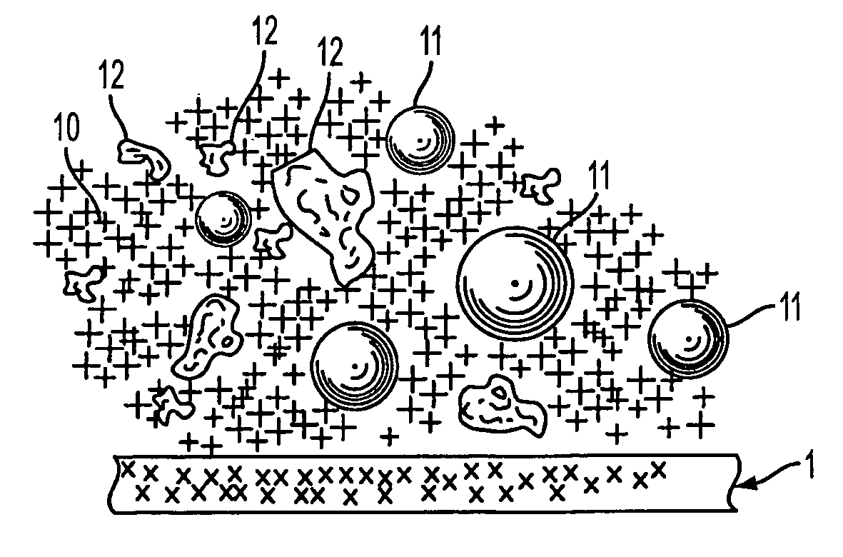
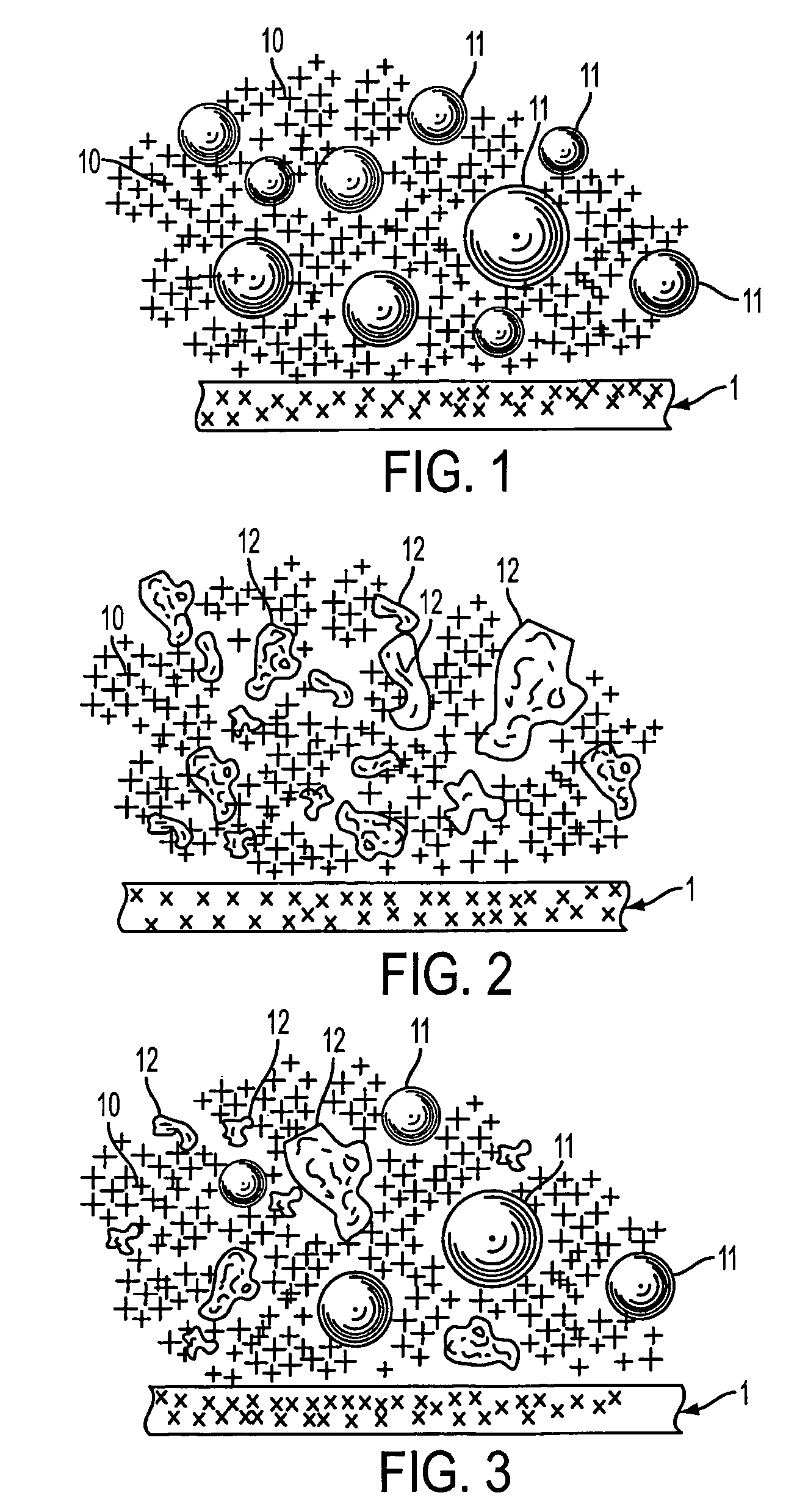
[0080]Laboratory measurements performed on various embodiments of this combination have shown a high-performance-to-weight ratio. In this example, the base polymer matrix was polyester and incorporated filler particles of differing acoustical impedances, high and low. The high-impedance filler was aluminum particles of random shape and varying in size from approximately 10-80 microns in their largest dimension; these occur in the composite matrix material in the proportion of five parts per hundred, by weight. The low-impedance filler was glass micro-balloons, spherical in shape and varying in size from approximately 10-80 microns in their largest dimension; these occur in the composite matrix material in the proportion of ten parts per hundred. This material, in laboratory measurements where artificial stiffness in the measurement method was introduced, produced 40+dB of acoustic attenuation.

example 2

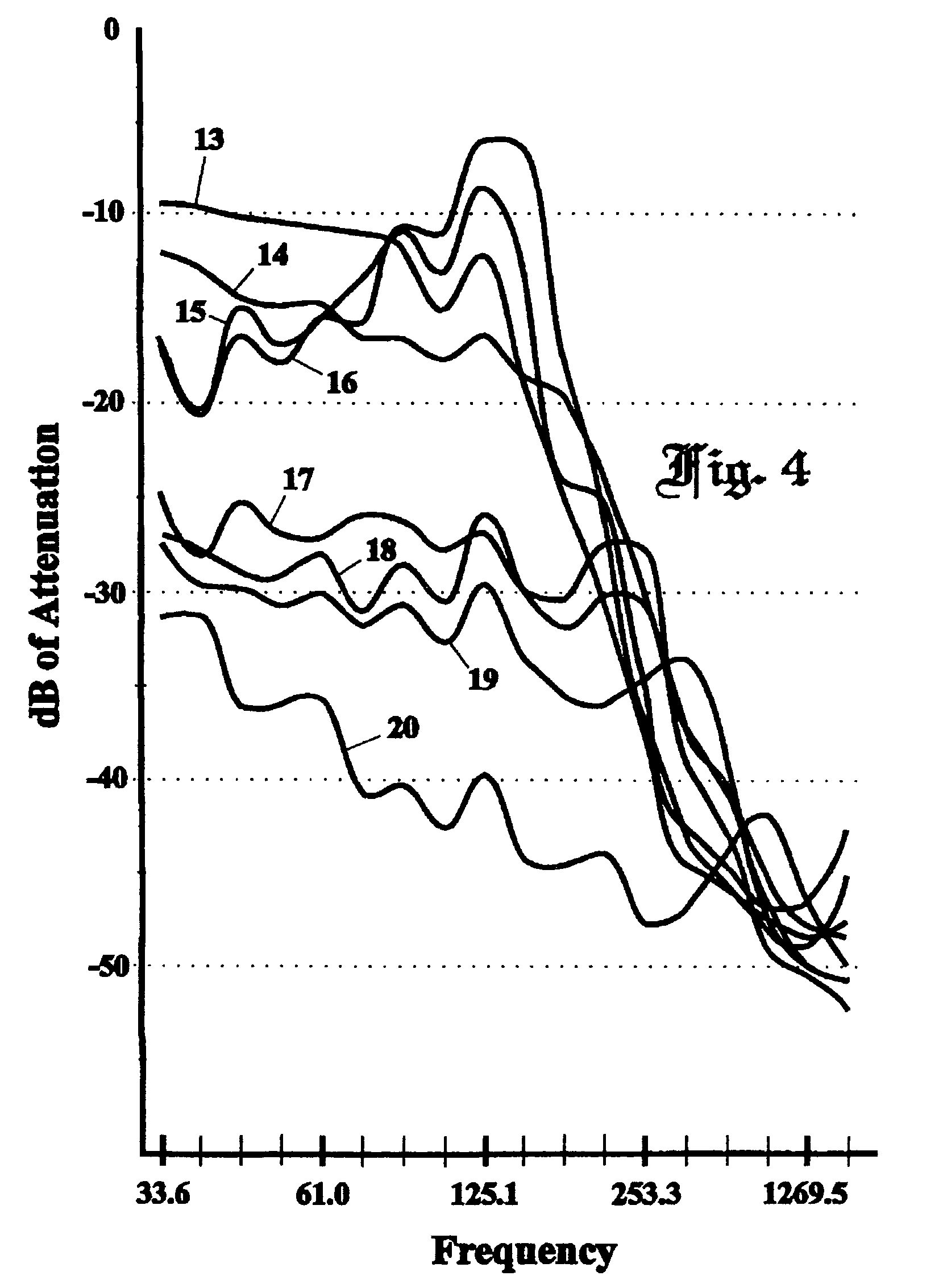
[0081]A silicone rubber material measuring approximately 0.20 inches in thickness and optimized in accordance with parameters set forth in the instant invention and U.S. Pat. No. 5,400,296 was affixed to one of three decoupling materials and placed on a vibrating surface to simulate a material mounted to a wall or floor containing structure-borne acoustical energy. Two of the decoupling matrices were urethane foams, one of which had been optimized and one which was unadulterated urethane. The third decoupler employed the teachings of the instant invention and was of a fibrous nature. The thickness of all the decouplers was approximately 0.25 inches. As can be seen from FIG. 11, at the lower frequencies of interest, the fiber decoupler yielded significantly better energy isolation than the two foam decouplers. At frequencies below 31.5 Hz, the non-optimized decoupler tended to provide slightly better isolation than the optimized foam. This tendency is supported by the fact that the o...


PUM

PropertyMeasurementUnit
frequenciesaaaaaaaaaa
diametersaaaaaaaaaa

Abstract

The present invention provides means of enhancing the acoustic attenuation and vibration damping of a material by (1) embedding a plurality of small particles of either a high characteristic acoustic impedance or a low characteristic acoustic impedance or combinations of high and low characteristic acoustic impedance materials to form a matrix material to act as a acoustic attenuator or vibration damper; and (2) combing this matrix material with a second layer of a decoupling material that serves to effectively isolate the matrix material and reduce its tendency to vibrate sympathetically to the impinging acoustic energy. The mass of the resultant material may be very low while retaining excellent acoustic attenuation, vibration damping, and structural characteristics.

Description

RELATED APPLICATIONS[0001]The instant application claims the benefit of Provisional Application No. 60 / 509,525, filed Oct. 9, 2003.BACKGROUND OF THE INVENTION[0002]1. Field of Invention[0003]The present invention relates generally to acoustic attenuation and vibration damping materials. More specifically, the invention provides a two-ply or greater composite acoustic attenuation and vibration damping material intended to be placed between acoustic and / or vibratory energy sources and acoustic and / or vibration protected areas.[0004]2. Description of the Related Art[0005]Within the field of noise control, absorptive techniques are typically utilized to prevent or reduce air-borne acoustic energy from reaching a receiving site. Similarly, vibration-damping techniques are usually applied in close contact with the vibrating structure to prevent or reduce air-borne or structure-borne energy from propagating to the protected area. Both techniques utilize internal damping of impinging acoust...

Claims


Application Information

Patent Timeline
Patent Type & Authority Patents(United States)
IPC IPC(8): G10K11/16E04B1/82E04B
CPCB32B5/16B32B5/24B32B5/30B32B7/02B32B27/18G10K11/162G10K11/168B32B2250/02B32B2260/025B32B2260/046B32B2260/048B32B2264/0292B32B2264/101B32B2264/105B32B2307/10B32B2307/102B32B2307/3065B32B2307/56B32B2605/003B32B2605/08
Inventor THOMAS, GERALD B.VAN DYKE, PAUL R.GUY, BRUCE
Owner THE GOVERNMENT OF THE UNITED STATES OF AMERICA AS REPRESENTED BY THE SEC OF THE NAVY NAVAL RES LAB WASHINGTON
Why Eureka
Try Eureka