Apparatus and method for generating a distributed clock signal

a distributed clock and signal technology, applied in the field of electronic circuits, can solve the problems of generating a number of problems for circuit designers and manufacturers, complicating the design of synchronization circuits, and adding unwanted latency to synchronization logic, so as to minimize the amount of latency

Inactive Publication Date: 2007-08-28
RAMBUS INC
View PDF27 Cites 23 Cited by
  • Summary
  • Abstract
  • Description
  • Claims
  • Application Information

AI Technical Summary

Benefits of technology

[0013]The present invention provides a method and apparatus for synchronizing signal transfers between two clock domains, where the clock domains have a gear ratio relationship. A gear ratio means that the clocks are related by a ratio, such that each clock has a different integer number of clock cycles in a common period. Also, in addition to a gear ratio relationship, the clocks may have a synchronized edge at the end of the common period. For each clock, the cycles in the common period are “colored”, i.e., identified by a number (1st, 2nd, etc.). By using the coloring technique, the appropriate clock edge to perform a data or control signal transfer can be identified. The edges are preferably chosen to minimize the latency of the transfer.
[0015]Conversely, for data transfers from the slow clock domain to the fast clock domain, the invention preferably uses the latest fast clock rising edge after a slow clock rising edge strobing in the data from the slow clock domain, but before the next slow clock rising edge strobing in the next data. Although the next fast clock edge could be used, since there are more fast clock edges than are needed for maximum slow clock bandwidth, the latest clock is chosen to maximize the data setup time.
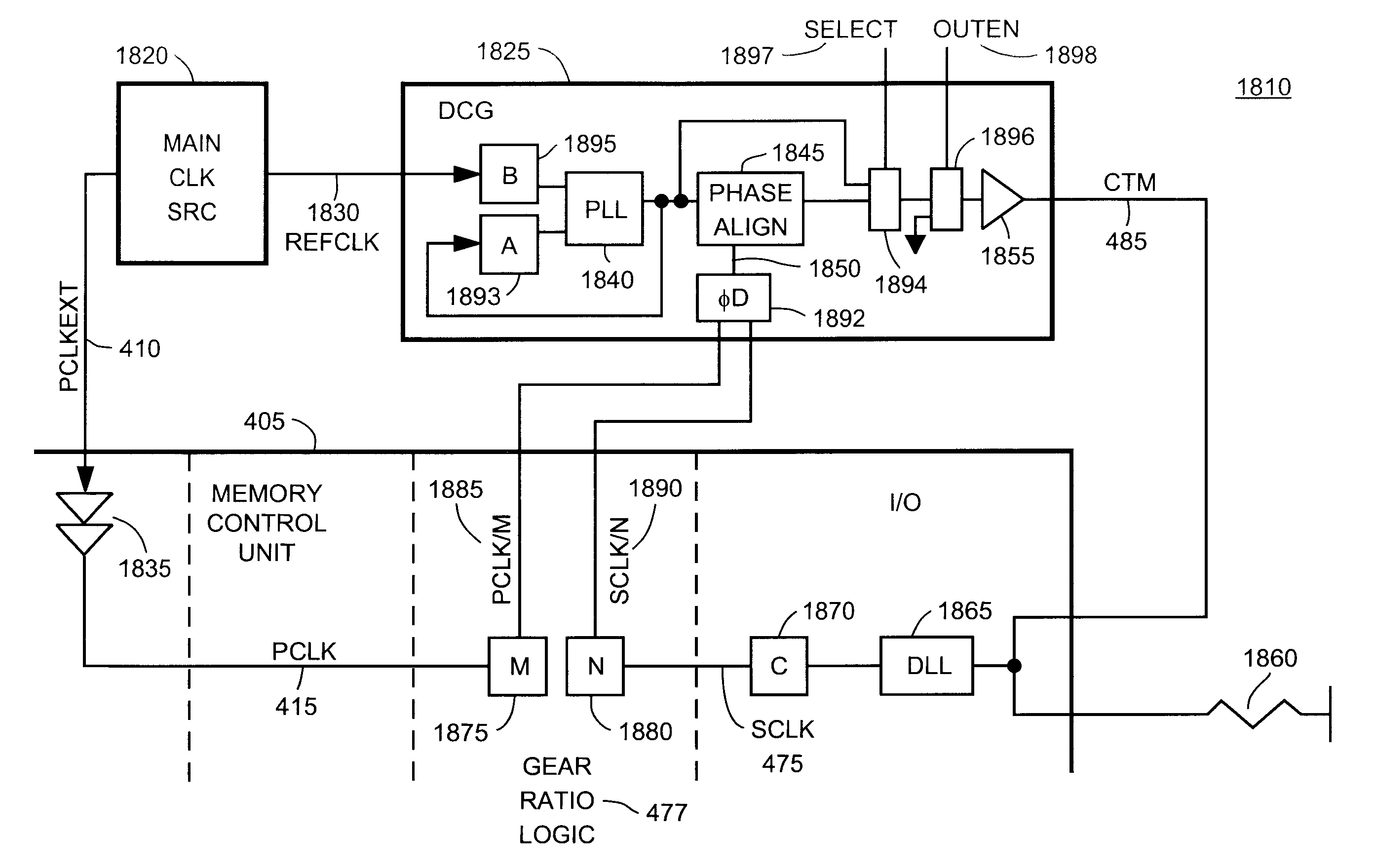
[0017]In yet another embodiment, the present invention provides a method and apparatus for a distributed clock generation loop which generates clock signals that allow asynchronous data transfers between different clock domains with minimized latency. This aspect is helpful, in part, because even if two clocks are related by a gear ratio, there is no inherent phase relationship between their phases. The distributed loop comprises at least one clock divider, a phase detector, and a variable delay element (phase aligner). For example, clock dividers are used to divide down the clocks that define the clock domains to a common frequency. The divided clocks drive a phase detector, which drives a phase aligner. The distributed loop shifts the phase of one of the divided clocks to align it with the other divided clock. When the divided clocks are phase aligned by the distributed loop, the original clocks will have edges which are also phase aligned. Data can then be transferred at the aligned clock edges without incurring additional latency for synchronization.
[0018]In one embodiment, in order to reduce power consumption in a low power mode, the output of a clock generator is disabled without disabling the clock generator in its entirety. This eliminates the power required to drive the load on the clock line, while avoiding frequency and phase drift, thus eliminating the latency normally required to re-acquire frequency and phase lock when coming out of a low power mode. This is accomplished by separating the phase alignment feedback and frequency lock feedback in one embodiment.
[0020]Therefore, the invention allows for synchronization of different clock domains, while minimizing the amount of latency resulting from any additional synchronization latency. A further understanding of the nature and advantages of the present invention may be realized by reference to the latter portion of the specification and attached drawings.

Problems solved by technology

The demands created by today's high-speed electronic equipment have generated a number of problems for circuit designers and manufacturers.
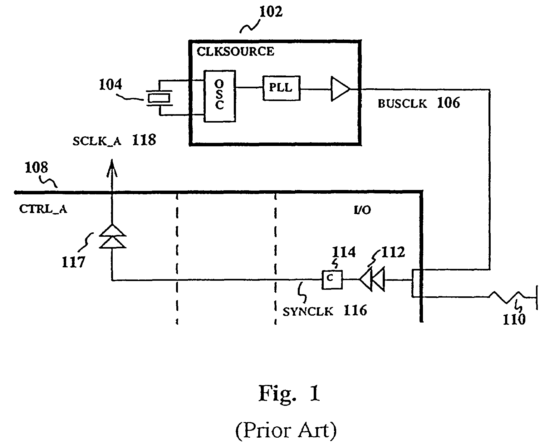
Unfortunately, the synchronization logic adds unwanted latency due to the additional circuitry.
Moreover, the disparity between the clock domains may include different frequencies and / or phases, further complicating the synchronization circuit design and adding to the latency.
Alternatively, eliminating one of the clock domains is not always feasible because there are practical limitations as to how many components a single clock source may support.
Also a single clock domain will limit the independent optimization of each subsystem.
However, it is very restrictive to require an entire system to run off one clock domain, and this approach is not practical for most systems.
For example, running the system using one clock signal will result in each subsystem not being optimized to its fullest potential.
While this synchronization is effective in solving some of the clock domain crossing problems, it adds additional latency to the data transfer.
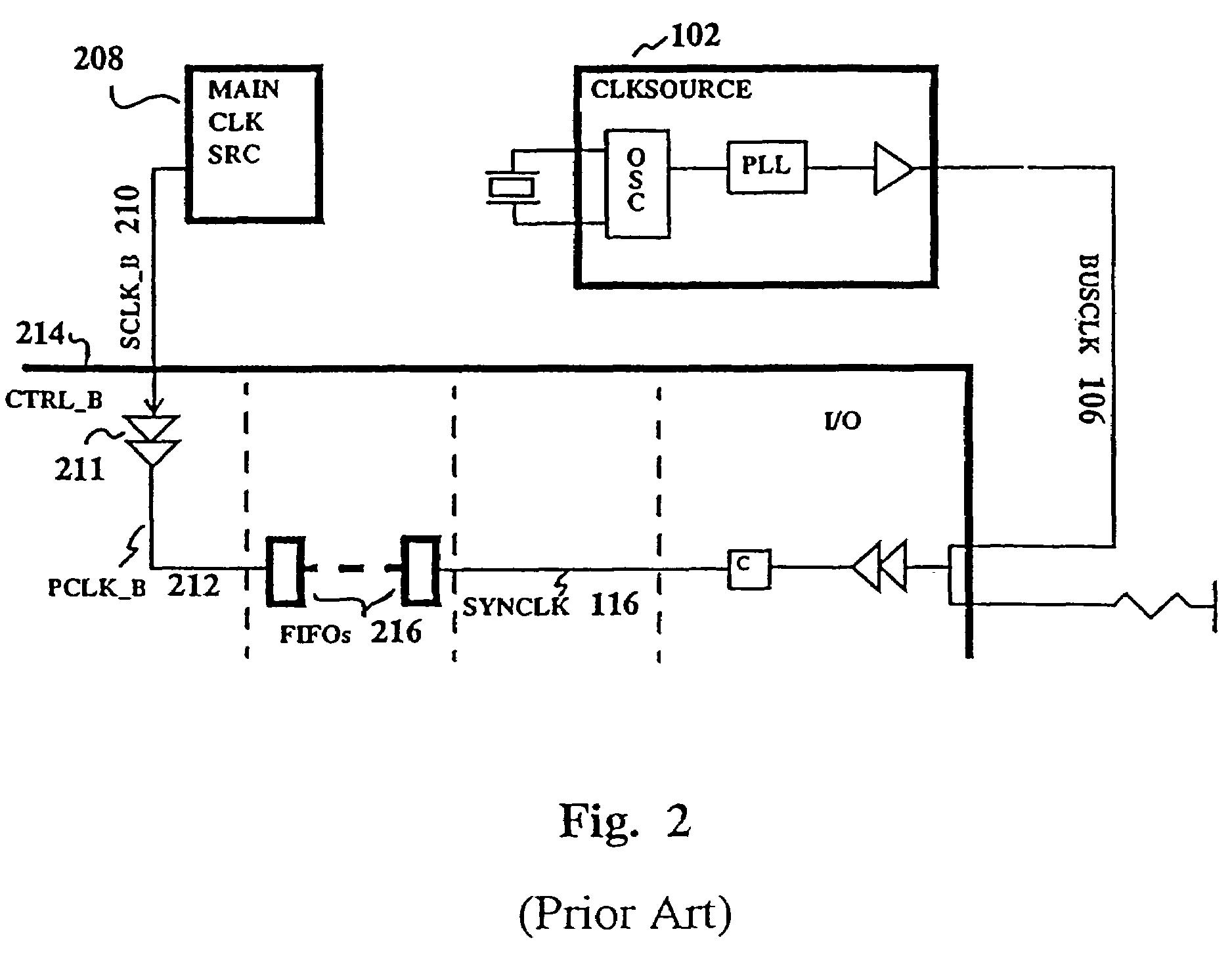
This solution is robust, but typically has a significant latency cost because of the synchronization delay.
Additionally, it can have a bandwidth cost if the empty-fill operations can not be overlapped because of synchronization overhead.

Method used


Image

  • Apparatus and method for generating a distributed clock signal
  • Apparatus and method for generating a distributed clock signal
  • Apparatus and method for generating a distributed clock signal

Examples


Embodiment Construction

[0042]One aspect of the present invention applies where the clock periods (or frequencies) of two domains of digital logic have a fixed ratio. When this relationship holds, the two domains are said to be operating in a gear ratio fashion. Therefore, two clocks can be said to have a gear ratio when an integer multiple of the first clock's period equals the same amount of time as an integer multiple of the second clock's period. For example, two clocks have a 4 / 3 gear ratio if four cycles of the first clock equal three cycles of the second clock.

[0043]FIG. 3 shows the clock waveforms of an example gear ratio where three cycles of clock PCLK_C 302 equal two cycles of clock SCLK_C 304, or 3* (cycle of PCLK_C)=2* (cycle of SCLK_C). In FIG. 3, PCLK_C 302 and SCLK_C 304 are phase aligned at the end of the common period, for example by being generated from the same crystal. Since gear ratio is defined as the ratio of the two clock frequencies, in the above example the gear ratio of PCLK_C / S...


PUM


Abstract

The present invention provides a method and apparatus for synchronizing signal transfers between two clock domains, where the clock domains have a gear ratio relationship. A gear ratio means that the clocks are related by a ratio, such that each clock has a different integer number of clock cycles in a common period. Also, in addition to a gear ratio relationship, the clocks may have a synchronized edge at the end of the common period. For each clock, the cycles in the common period are “colored”, i.e., identified by a number (1st, 2nd, etc.). By using the coloring technique, the appropriate clock edge to perform a data or control signal transfer can be identified. The edges are preferably chosen to minimize the latency of the transfer.

Description

RELATED APPLICATIONS[0001]This application is a continuation of U.S. patent application Ser. No. 10 / 091,979, filed Mar. 4, 2002, now U.S. Pat. No. 6,836,521, which is a divisional of U.S. patent application Ser. No. 09 / 169,589, filed Oct. 9, 1998, now U.S. Pat. No. 6,396,887, which claims priority to U.S. Provisional Patent Application No. 60 / 062,035, filed on Oct. 10, 1997, all of which are incorporated herein by reference.TECHNICAL FIELD[0002]The present invention relates to electronic circuits and the field of distributed clock circuits. More particularly, the present invention relates to a method and circuit for synchronizing clock signals from separate clock domains with minimized latency.BACKGROUND[0003]The demands created by today's high-speed electronic equipment have generated a number of problems for circuit designers and manufacturers. For example, many applications require that two subsystems running at different frequencies communicate with each other. Generally, logic ...

Claims


Application Information

Patent Timeline
Patent Type & Authority Patents(United States)
IPC IPC(8): H04L7/00G06F1/12G06F5/06G06F7/68G06F13/42
CPCG06F1/12G06F5/06G06F7/68G06F13/4243
Inventor WARE, FREDERICK A.DONNELLY, KEVIN S.TSERN, ELY K.NIMMAGADDA, SRINIVAS
Owner RAMBUS INC
Why Eureka
Try Eureka