Penetration type washing machine, method for controlling the same, and tub cover for the same

a washing machine and penetration type technology, applied in the direction of washing machines with receptacles, spin-dryers, caps, etc., can solve the problems of poor washing efficiency, entanglement or damage of laundry, and difference between washed and non-washed parts of washing

Inactive Publication Date: 2007-09-04
LG ELECTRONICS INC
View PDF46 Cites 14 Cited by
  • Summary
  • Abstract
  • Description
  • Claims
  • Application Information

AI Technical Summary

Benefits of technology

[0019]An object of the invention is to solve at least the above problems and / or disadvantages and to provide at least the advantages described hereinafter.

Problems solved by technology

However, the related art washing machines, making the washing mostly using mechanical energies, of such as pulsator or agitator, is required to have a rotating power of a certain speed for making an adequate washing, that causes entangle of or damage to the laundry.
Therefore, the related art penetration type washing machine has problems in that a complicated system and a large sized pump for obtaining a spraying power for the washing are required.
First, as the inner tub rotates only in one direction, the washing water penetrates a fixed position of the laundry, to cause a wash difference in which a washed portion and a non-washed portion are happened.
Second, the only use of penetration washing makes a washing efficiency poor. Because, though the penetration type washing machine can prevent damage to, and entangling of the laundry, in general, the washing efficiency is poor compared to the pulsator type washing machine.
Third, since the washing machine fails to provide a guide means for guiding the washing water to an inside surface of the inner tub when the washing water is pumped to an upper portion between the inner tub and the outer tub, and then, circulated into the inner tub, the washing machine has a poor pumping efficiency.
Use of a related art tub cover for the penetration type washing machine causes leakage of spray of the washing water.
Moreover, the leaked or splashed washing water to outside of the outer tub 102 wets various electric components of the washing machine, that is liable to cause malfunction or disorder of the washing machine.

Method used


Image

  • Penetration type washing machine, method for controlling the same, and tub cover for the same
  • Penetration type washing machine, method for controlling the same, and tub cover for the same
  • Penetration type washing machine, method for controlling the same, and tub cover for the same

Examples


first embodiment

[0079]That is, similar to the related art tub cover, the first embodiment tub cover 400 includes an upper surface portion 411, a tight fit portion 413, and a fastening portion 412. However, different from the related art, the fastening portion 412 has a downward projection at an approx. center thereof in parallel to the tight fit portion 413, and there is a slot on a top portion of the outer tub 102 for insertion of the projection 415 thereto. And, there is a sealing member 417 in a space formed between the tight fit portion 413 and the projection 415 for prevention of leakage.

[0080]And, referring to FIG. 5, a length of the projection 415 may be formed shorter, for providing the sealing member 417 in a space formed below the projection 415.

[0081]And, as shown in FIG. 6, the sealing member may be disposed on a top end of the outer tub 102. In detail, as the sealing member 417 is fitted to the top end of the outer tub 102, a support 102b is projected in an outward radial direction of ...

second embodiment

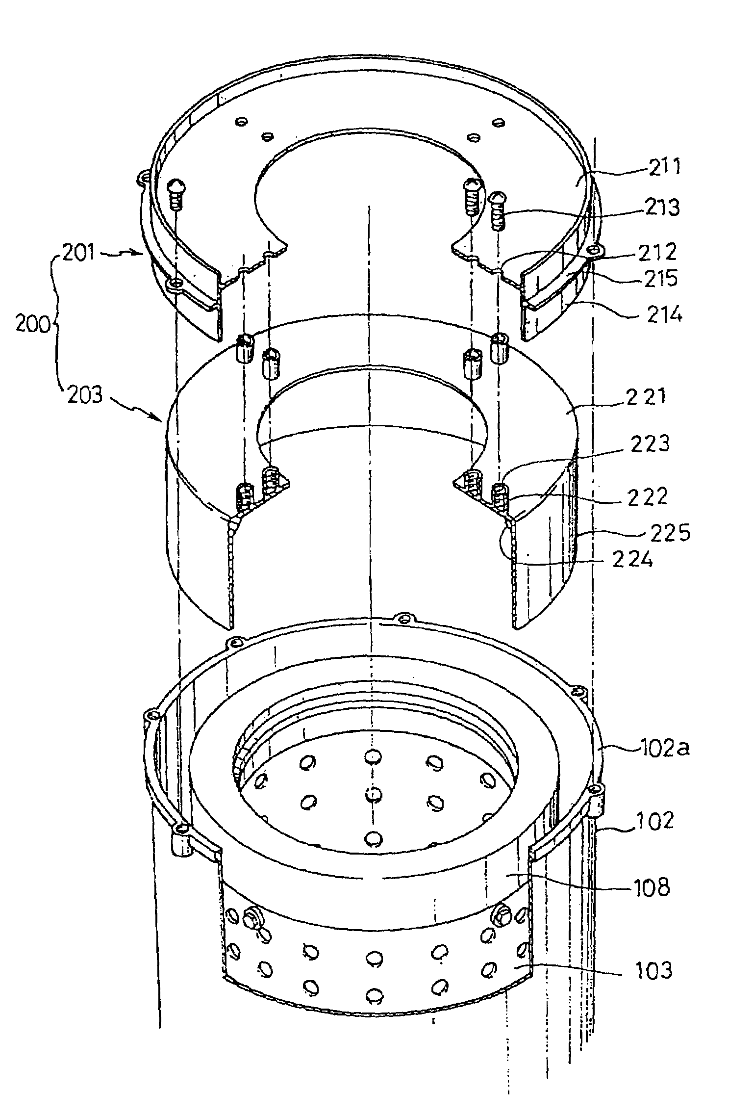
[0083]The second embodiment tub cover 200 includes an upper tub cover 201 fastened to the outer tub 102, and a lower tub cover 203 mounted under the upper tub cover 201 with a space therefrom, wherein there are washing water guide passages P1 and P2 formed between the upper and lower tub covers. The upper tub cover 201 has a substantially annular form of an upper surface portion 211, a tight fit portion 214 projected from an outer end of the upper surface portion 211 vertically for tight fit to an inside wall of the outer tub 102, and a fastening portion 215 extended from the tight fit portion 214 in a horizontal direction for fastening to a top end of the outer tub, forming an “L” section, substantially. The lower tub cover 203 has an upper surface portion 221, and a vertical portion 225 projected downward from an outer end of the upper surface portion 221, with a plurality of reinforcing brackets 224 connected between the upper surface portion and the vertical portion. There are a...

third embodiment

[0085]A tub cover having modified such drawback is the third embodiment tub cover, which will be explained with reference to FIGS. 10˜11.

[0086]The third embodiment tub cover 300 includes an upper surface portion 301 and a tight fit portion 303, and there are a plurality of deflectors 302 on an underside of the upper surface portion 301 for deflecting a flow direction of the washing water. The deflector 302 is fitted in a radial direction for deflecting the washing water advancing in a tangential direction to a center direction. There are a plurality of deflectors fitted as fixed intervals to divide the flow paths. As shown in FIG. 12, this structure permits the washing water pumped and flowed into the tub cover 300 hits the deflectors 302, to change a direction of flow toward, not the tangential direction, but the center direction, substantially. And, as shown in FIG. 13, there may be a guide rib 305 on the deflector 302 for reducing a friction of the washing water. And, a plate dro...


PUM


Abstract

Method for controlling a full automatic washing machine, the method comprising a washing cycle, a rinsing cycle, and a dewatering cycle, wherein the washing or the rinsing cycle includes the step of rotating an inner tub at a high speed higher than a preset speed in one direction, thereby making a centrifugal force caused by high speed rotation of the inner tub, to push laundry against a wall of the inner tub, to enforce washing water in the inner tub to penetrate through the laundry at a speed higher than required to make the washing done, and to pump the washing water penetrated through the laundry and discharged into an outer tub upward, to recirculate to the inner tub.

Description

[0001]This application is a Divisional of application Ser. No. 10 / 052,246, filed Jan. 23, 2002 now U.S. Pat. No. 6,668,410, which in turn is a Divisional of application Ser. No. 09 / 376,375 filed Aug. 18, 1999, now U.S. Pat. No. 6,351,974, the entire disclosures of which are hereby incorporated by reference.BACKGROUND OF THE INVENTION[0002]1. Field of the Invention[0003]The present invention relates to a full automatic washing machine, and more particularly, to a penetration type washing machine which makes washing by penetrating washing water through laundry; a method for controlling the same; and, a tub cover for the same.[0004]2. Background of the Related Art[0005]Being a device for peeling off contaminant by applying energies, such as impact, to the laundry, there are pulsator washing machines, drum washing machines, agitator washing machine, and the like according to types of energy application. Washing of the laundry is made by applying impacts to the laundry using pulsator or ...

Claims


Application Information

Patent Timeline
Patent Type & Authority Patents(United States)
IPC IPC(8): D06F23/04D06F37/12D06F35/00D06F33/02D06F39/08
CPCD06F35/006
Inventor LYU, JAE CHEOLCHO, SUNG JINRYU, HYUNG DAEKANG, CHANG SIKKIM, JI MAENG
Owner LG ELECTRONICS INC
Why Eureka
Try Eureka