Shock resistant box

a box and shock-resistant technology, applied in the field of boxes, can solve the problems of affecting the protection of boxes, affecting the quality of boxes, so as to reduce shipping damage to boxes, and reduce the need for thick internal padding

Active Publication Date: 2007-09-04
ALPHA PACKAGING INC +1
View PDF8 Cites 74 Cited by
  • Summary
  • Abstract
  • Description
  • Claims
  • Application Information

AI Technical Summary

Benefits of technology

[0009]The present invention relates to methods and apparatus for reducing damage to items shipped in corrugated boxes as described below, and for reducing shipping damage to the boxes themselves while reducing the need for thick internal padding in the box. Damage to box contents is reduced by incorporating at least one relatively thin planar damped panel substantially par

Problems solved by technology

Corrugated cardboard boxes offer limited protection from shipping damage, but their low cost and ready availability make them attractive for many one-way shipments.
Shocks due to rough handling of truck, rail and aircraft shipments impart kinetic energy to a box that may damage its contents unless the energy is effectively redistributed and dissipated by the box and internal packing materials, rather than being applied to the item(s) to be protected.
But the poor energy redistribution that is common in cardboard boxes means that some portions of box walls and packing materials may be overstressed and substantially destroyed while other portions remain undamaged.
Unfortunately, failure of the overstressed portions may allow transmission of imparted energy to contents that the box was intended to protect.
Even if the box contents arrive at their destination undamaged, the box and/or its internal packing may be sufficiently degraded to prevent their use for returning defective goods for repair.
But field experience showed that the disparity between side wall thickness (i.e., four corrugated layers) and top and bottom wall thickness (i.e., a single corrugated layer) made the modified box especially susceptible to shipping shocks applied to either the top or bottom

Method used


Image

  • Shock resistant box
  • Shock resistant box
  • Shock resistant box

Examples


Embodiment Construction

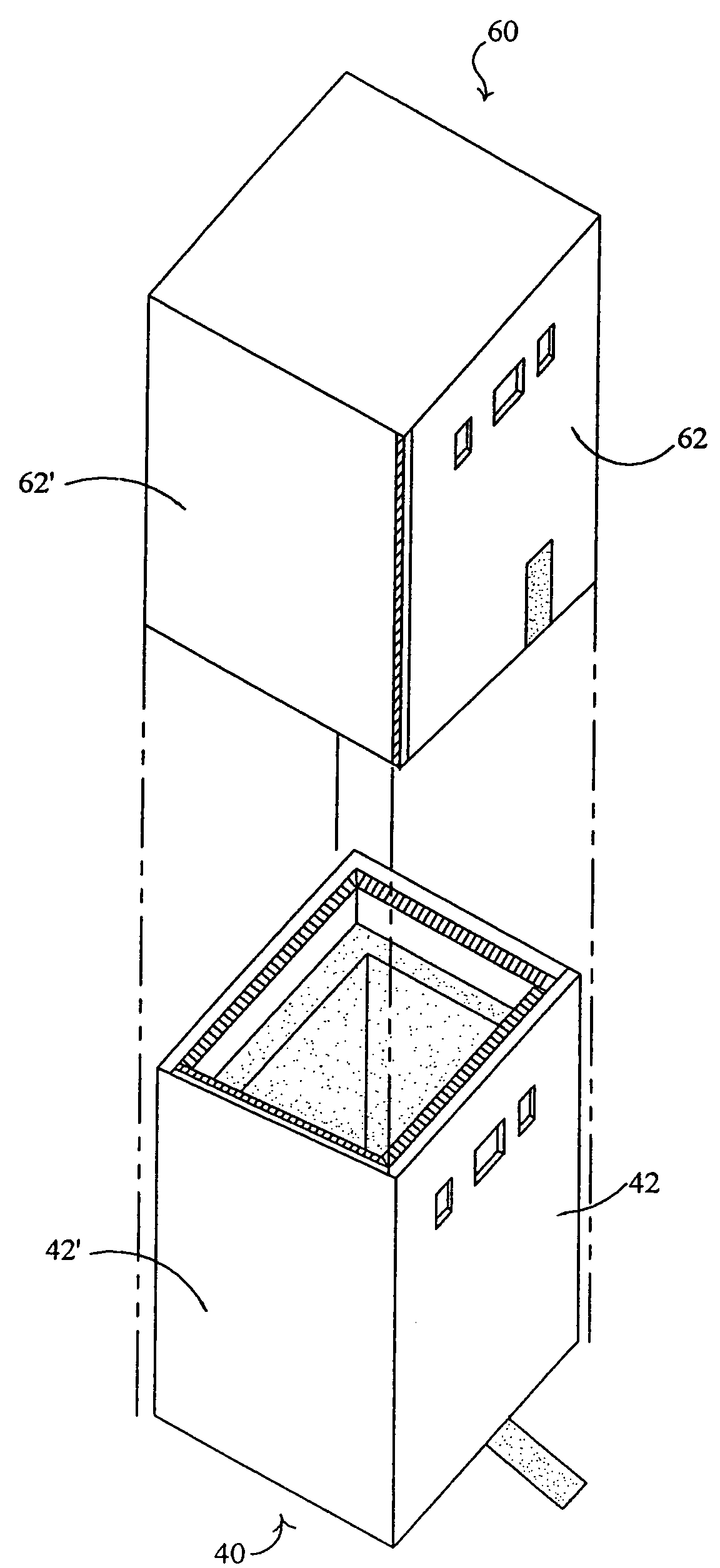
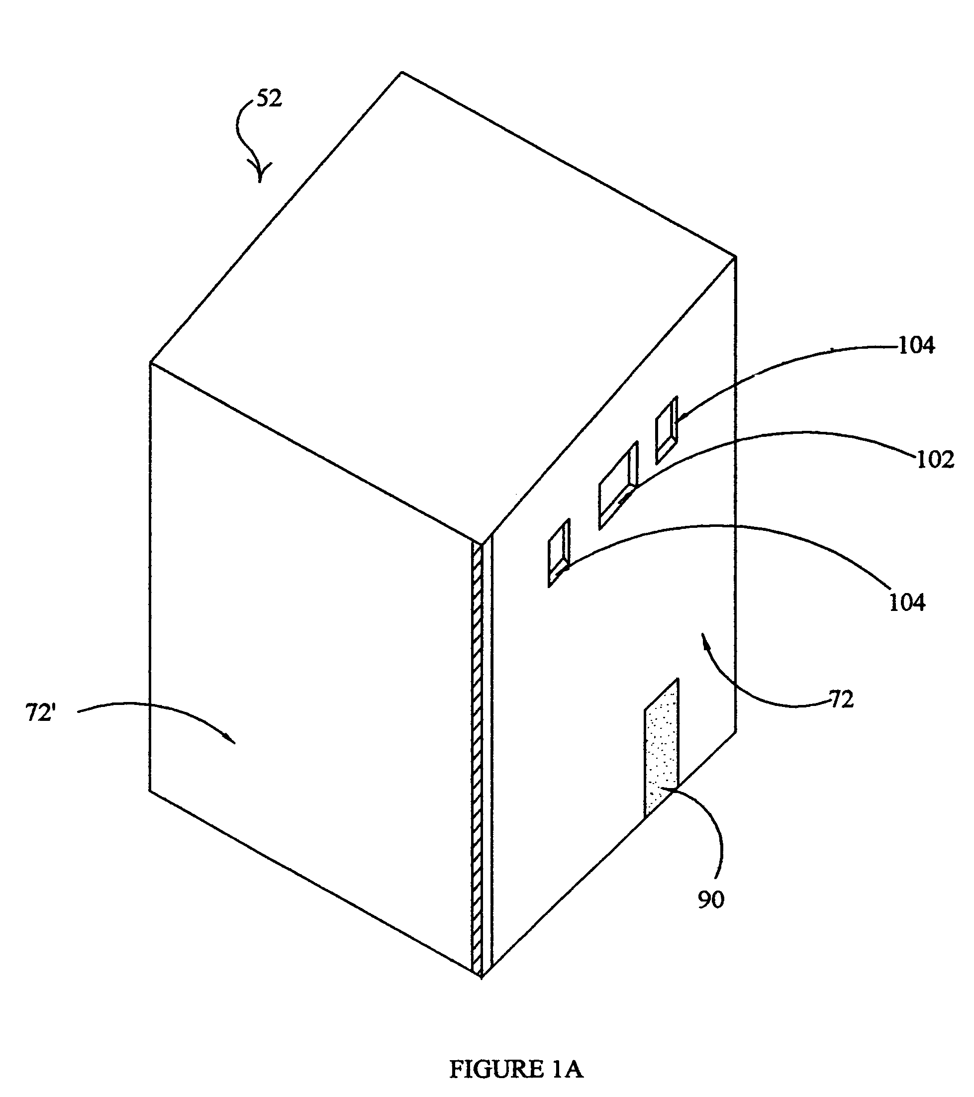
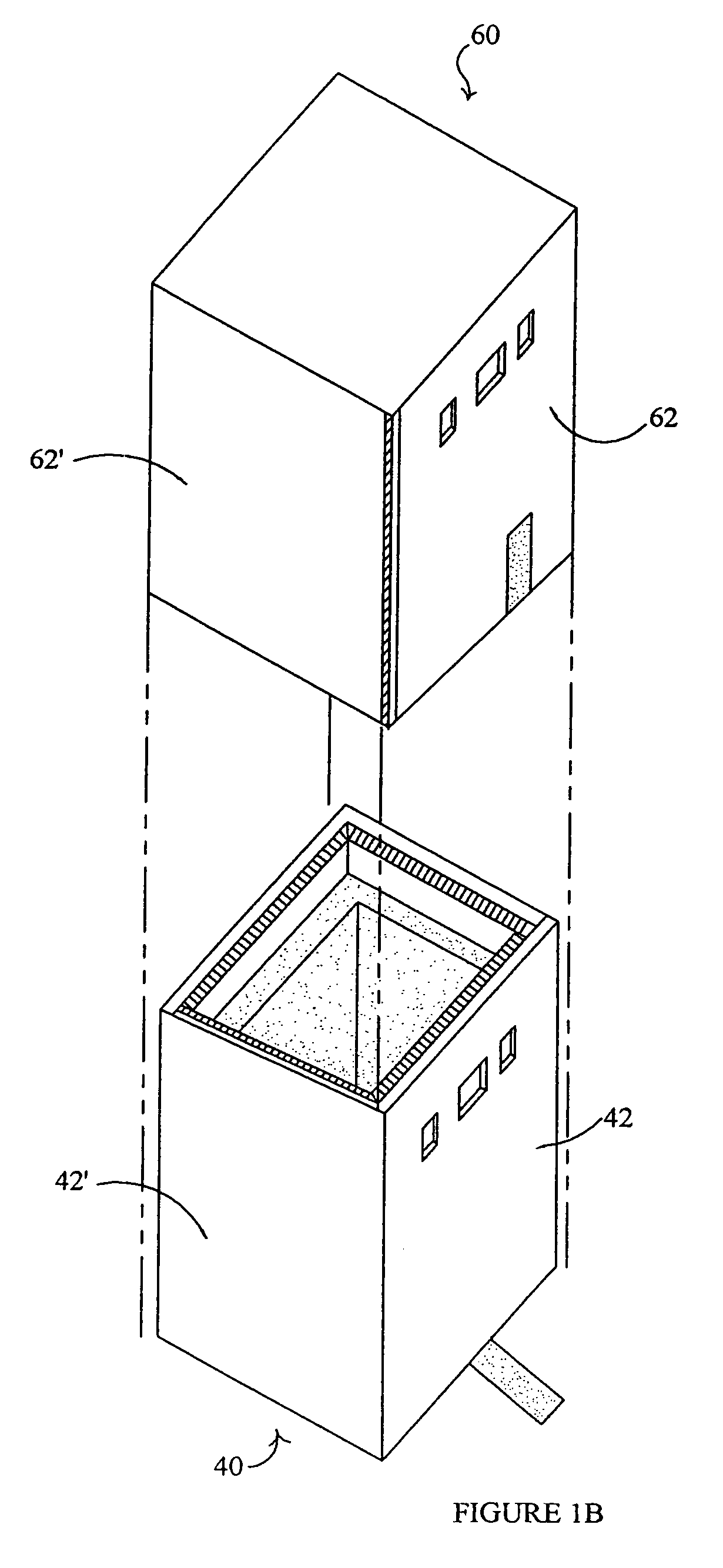
[0028]FIG. 1A schematically illustrates a shipping box assembly 52 with the upper portion thereof telescoped over the lower portion and secured by hook and eye releasable and reusable closure means 90. FIG. 1B schematically illustrates an exploded view of the box assembly 52 comprising a top portion 60 and a bottom portion 40. Top portion 60 comprises four top-portion side walls (shown in plan section in FIG. 3A in the form of a first substantially similar opposing pair of top-portion side walls 62,62 plus a second substantially similar opposing pair of top-portion side walls 62′,62′), and a top-portion top wall 64 (shown in elevation section in FIG. 2). As shown in FIG. 1A, top portion 60 and bottom portion 40 are each shaped as a hollow open-ended rectangular parallelepiped. Bottom portion 40 comprises four bottom-portion side walls (shown in plan section in FIG. 3B in the form of a first substantially similar opposing pair of bottom-portion side walls 42,42 plus a second substant...


PUM


Abstract

Methods and apparatus are described for reducing damage to items shipped in corrugated boxes, and for reducing damage to the boxes themselves and the packing material within them. Damage is limited by adding one or more planar damped panels to a box for redistributing kinetic energy absorbed by the box when it is subjected to characteristic shipping shock and vibration. Efficient coupling of redistributed kinetic energy to resilient packing material within a box allows the use of relatively less resilient padding surrounding shipped items, thus allowing use of a relatively smaller box to obtain an acceptable level of protection. Planar damped panels also limit shifting of the item(s) to be protected by acting as damped variable-rate springs.

Description

FIELD OF THE INVENTION[0001]The invention relates generally to boxes. More particularly, the invention relates to corrugated boxes having structural features for reducing shipping damage to box contents.BACKGROUND[0002]Corrugated cardboard boxes offer limited protection from shipping damage, but their low cost and ready availability make them attractive for many one-way shipments. Shocks due to rough handling of truck, rail and aircraft shipments impart kinetic energy to a box that may damage its contents unless the energy is effectively redistributed and dissipated by the box and internal packing materials, rather than being applied to the item(s) to be protected. Dissipation of imparted kinetic energy is typically manifest in localized flexing, crushing or disintegration of portions of box walls and / or packing materials. But the poor energy redistribution that is common in cardboard boxes means that some portions of box walls and packing materials may be overstressed and substanti...

Claims


Application Information

Patent Timeline
IPC IPC(8): B65D5/42
CPCB65D5/566B65D5/68B65D81/022Y10S229/939
Inventor BENSON, MIRIAM M.BRAMBLE, RONALD L.
Owner ALPHA PACKAGING INC
Why Eureka
Try Eureka