Optical adjustment of working range and beam spot size in electro-optical readers

a technology of optical adjustment and beam spot size, applied in the field of optical adjustment of working range and beam spot size in electro-optical readers, can solve the problems of consuming electrical power, affecting the reading accuracy of indicia, generating dust to obscure the optics,

Active Publication Date: 2007-09-04
SYMBOL TECH LLC
View PDF12 Cites 58 Cited by
  • Summary
  • Abstract
  • Description
  • Claims
  • Application Information

AI Technical Summary

Benefits of technology

[0019]One object of this invention is to provide an improved arrangement for and method of adjusting the working range and / or beam spot size of a reader for reading a data-encoded symbol.
[0020]Another object of this invention is to provide an arrangement which is compact, lightweight, durable and efficient in construction and quiet and reliable in operation, and thus is ideally suited for portable hand-held applications.
[0028]The changing between different focal planes and / or the changing of the beam cross-section is performed without mechanically or physically moving solid lenses, thereby decreasing the noise and vibration and dust in such readers, as well as the size, weight, power and volume requirements. The variable liquid lens will not wear out over time.

Problems solved by technology

This is disadvantageous for several reasons.
First, the mechanical movement generates vibrations which are propagated through the reader to the user's hand, and may also generate dust to obscure the optics.
Moreover, depending on the scan rate, the vibrations can generate objectionable, annoying, audible hum.
In addition, the lens movement requires a drive which, in turn, consumes electrical power, is expensive and slow, can be unreliable, occupies space and increases the overall weight, size and complexity of the reader.

Method used


Image

  • Optical adjustment of working range and beam spot size in electro-optical readers
  • Optical adjustment of working range and beam spot size in electro-optical readers
  • Optical adjustment of working range and beam spot size in electro-optical readers

Examples


Embodiment Construction

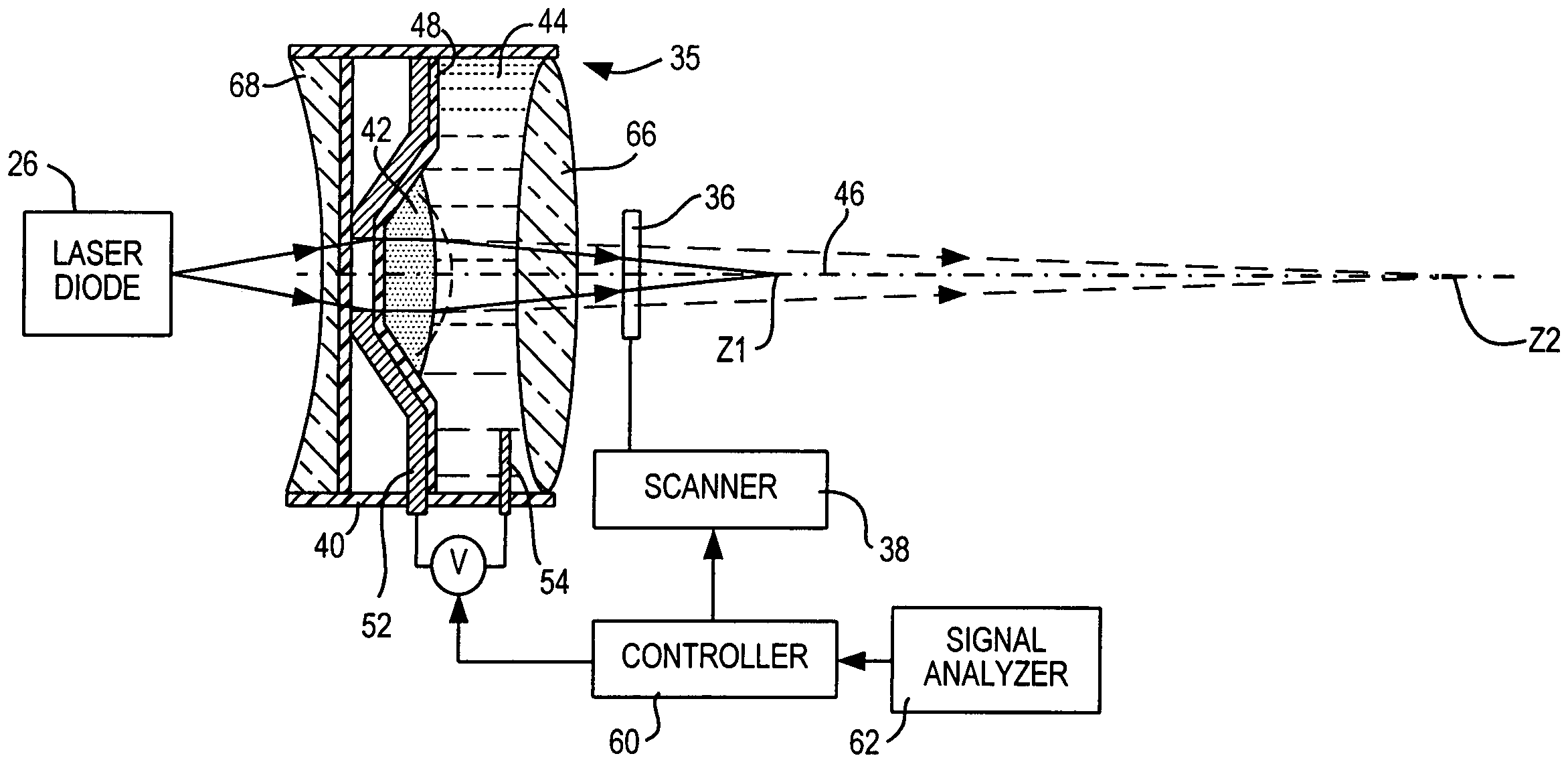
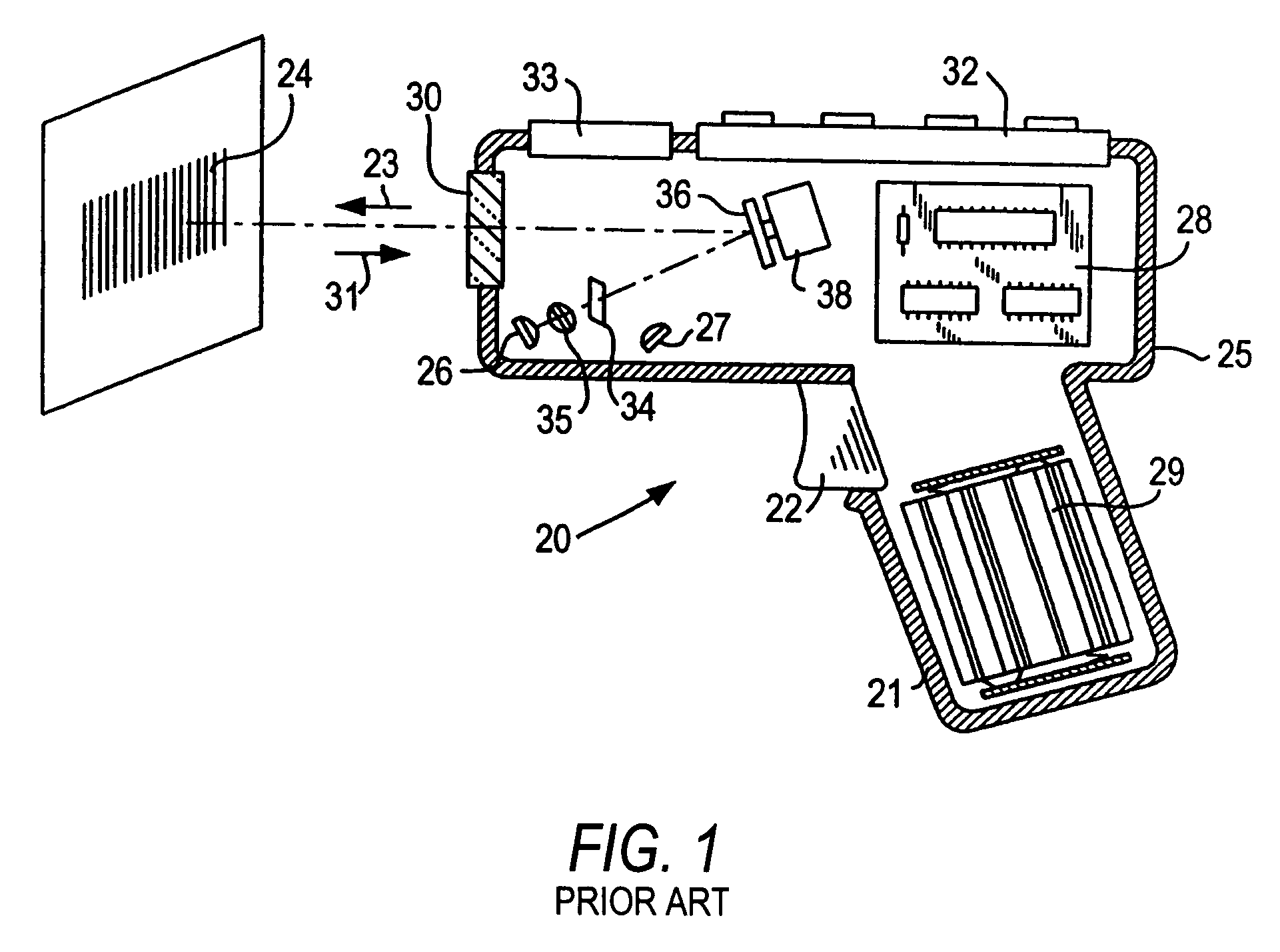
[0037]Reference numeral 20 in FIG. 1 generally identifies a hand-held reader for electro-optically reading indicia, such as bar code symbol 24, located in a range of working distances therefrom. The reader 20 has a pistol grip handle 21 and a manually actuatable trigger 22 which, when depressed, enables a light beam 23 to be directed at the symbol 24. The reader 20 includes a housing 25 in which a light source 26, a light detector 27, signal processing circuitry 28, and a battery pack 29 are accommodated. A light-transmissive window 30 at a front of the housing enables the light beam 23 to exit the housing, and allows light 31 scattered off the symbol to enter the housing. A keyboard 32 and a display 33 may advantageously be provided on a top wall of the housing for ready access thereto.

[0038]In use, an operator holding the handle 21 aims the housing at the symbol and depresses the trigger. The light source 26 emits a light beam which is optically modified and focused by an optical ...


PUM

PropertyMeasurementUnit
diameteraaaaaaaaaa
frequencyaaaaaaaaaa
frequencyaaaaaaaaaa

Abstract

Working range and laser beam cross-section are adjusted in an electro-optical reader for reading indicia by applying control voltages to a pair of variable lenses to change the shape of a liquid therein. An aperture stop maintains a constant beam cross-section as an input to one of the lenses.

Description

CROSS-REFERENCE TO RELATED APPLICATION[0001]This application is a continuation-in-part of U.S. patent application Ser. No. 10 / 798,498, filed Mar. 11, 2004 now U.S. Pat. No. 7,201,318, and commonly assigned therewith.BACKGROUND OF THE INVENTION[0002]1. Field of the Invention[0003]The present invention generally relates to electro-optical systems for reading indicia, for example, bar code symbols, having parts with different light reflectivities and, in particular, to an arrangement for, and a method of, adjusting the working range and / or the laser beam cross-section for increased performance in the system.[0004]2. Description of the Related Art[0005]Various electro-optical readers and systems have previously been developed for reading bar code symbols appearing on a label, or on a surface of a target. The bar code symbol itself is a coded pattern of indicia. Generally, the readers electro-optically transform graphic indicia of the symbols into electrical signals which are decoded int...

Claims


Application Information

Patent Timeline
Patent Type & Authority Patents(United States)
IPC IPC(8): G06K7/10G06K7/14G02B26/10G02B3/14G02B26/00G02B26/02G02B26/08G02B27/09G02F1/00G03B3/10
CPCG02B3/14G02B26/005G06K7/10702
Inventor BARKAN, EDWARD
Owner SYMBOL TECH LLC
Why Eureka
Try Eureka