Aerofoils

a technology of aerofoil and aerosol, which is applied in the direction of machines/engines, air-flow influencers, liquid fuel engines, etc., can solve the problems of erosion, unfavorable aerofoil wear, and inability to lend themselves readily

Active Publication Date: 2007-09-04
LEONARDO MW LTD
View PDF20 Cites 9 Cited by
  • Summary
  • Abstract
  • Description
  • Claims
  • Application Information

AI Technical Summary

Benefits of technology

[0008]Thus the exact desired shape of an opening from the passage, to achieve a desired airflow affecting characteristic, may be more easily provided by the provision of the outlet fitting. The fitting may be made in a durable material which is more resistant to erosion than the materials of the body, and fitted to the aerofoil surface so that the interface between the fitting and the upper aerofoil surface is smooth, i.e. so that no or a minimal discontinuity is provided.
[0013]The flexible conduit, which may be a plastic such as polyurethane, thus will allow optimised airflow through the passage, as the conduit may smooth any otherwise abrupt changes of direction of the airflow. Of course where an inlet fitting is provided, the flexible conduit may be integral with the inlet fitting or connected to the inlet fitting as desired.

Problems solved by technology

Such materials do not readily lend themselves to the formation of accurately shaped openings, and moreover, the provision of a discontinuity such as an opening, can lead to erosion and other undesirable aerofoil wear, particularly in the region of the opening.

Method used


Image

  • Aerofoils
  • Aerofoils
  • Aerofoils

Examples


Embodiment Construction

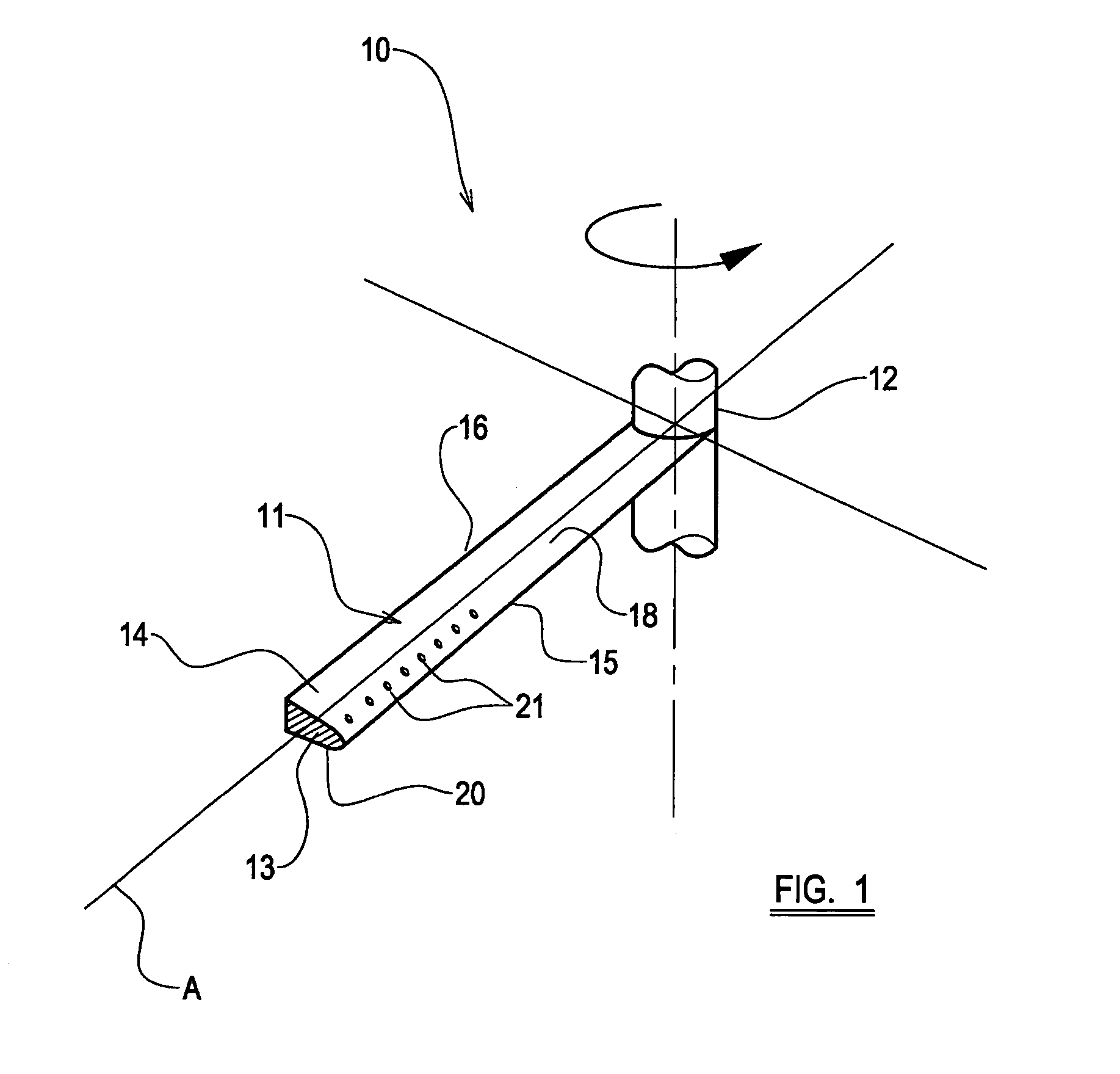
[0026]Referring to the drawings, a main sustaining rotor assembly 10 of a helicopter has four blades, one of which is shown at 11, and the positions of the other blades being indicated by lines.

[0027]The blade 11 is an aerofoil over which in use, air flows to provide lift.

[0028]The rotor blade 11 extends from a root end 12 which typically is a rotor head or hub, outwardly along a blade span to a tip which is indicated at 13. In practice the tip 13 would be of a complex configuration but is shown in FIG. 1 schematically only to indicate the aerofoil cross section.

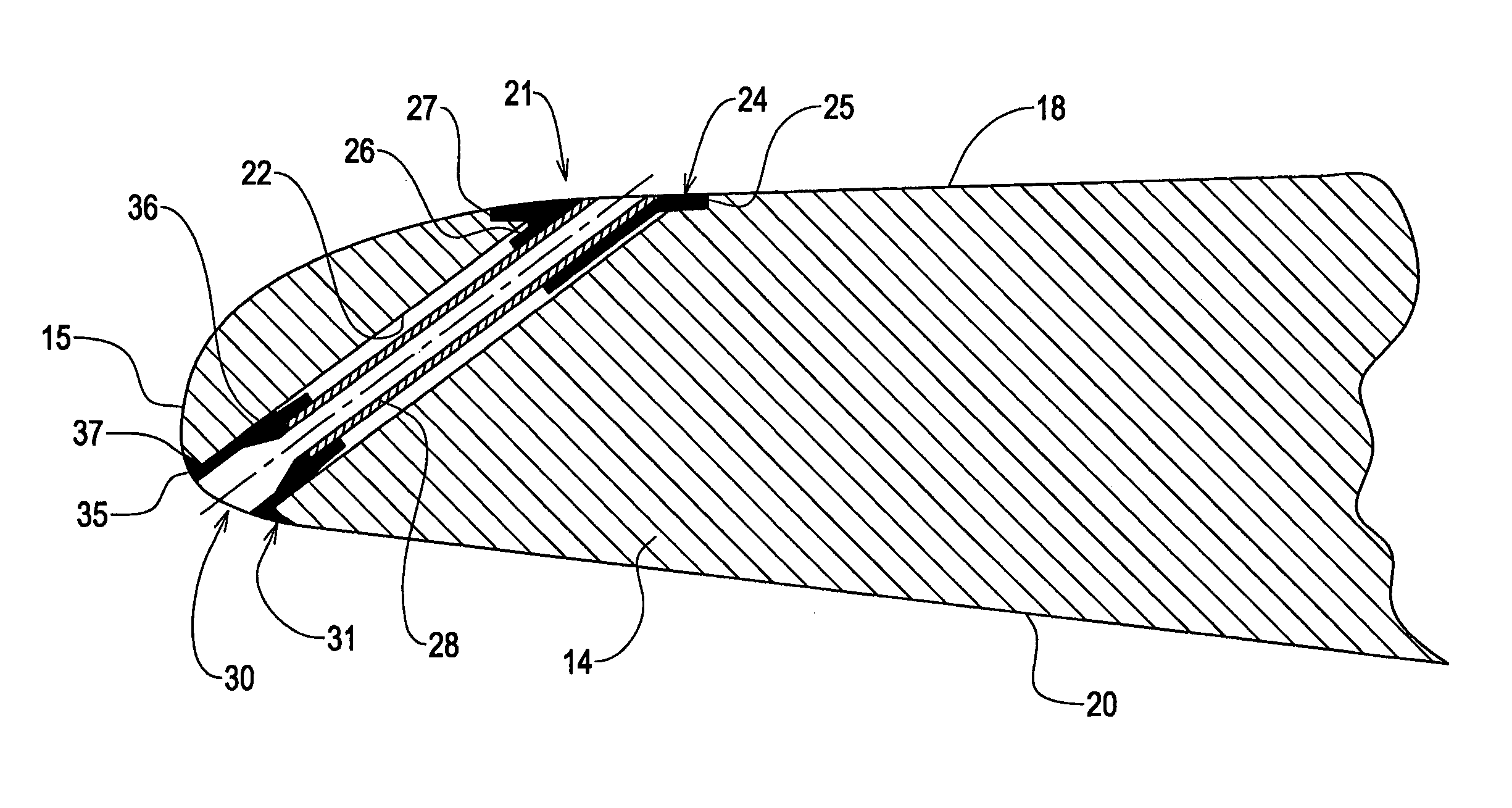
[0029]The blade 11 has an aerofoil body 14, with a leading edge 15, a trailing edge 16, an upper aerofoil surface 14 between the leading and trailing edges 15, 16, and a lower aerofoil surface 20 between the leading and trailing edges 15, 16.

[0030]In use, the blade 11 may be feathered about a blade axis A and thus the angle of incidence of the blade 11 to the air through which the blade 11 in use moves, may vary.

[0031]To del...


PUM


Abstract

An aerofoil has a body, and at least one flow control device, the flow control device including a passage within the body of the aerofoil, and a passage outlet at an upper aerofoil surface of the aerofoil, whereby in use, air from the passage passes through the passage outlet to affect airflow over the upper surface of the aerofoil over at least a range of incidence angles, wherein the passage outlet is provided by an outlet fitting which is secured relative to the upper surface of the aerofoil, the outlet fitting including a surface part which lies contiguously with the surrounding upper aerofoil surface so there is no or only a minimal discontinuity where the surface part and the surrounding upper aerofoil surface interface, the surface part of the fitting further including an opening which communicates with the passage within the body of the aerofoil.

Description

BACKGROUND TO THE INVENTION[0001]This invention related to an aerofoil having a flow control device commonly known as a air jet vortex generator or AJVG.[0002]An AJVG typically includes a passage within the aerofoil, the passage opening at an upper aerofoil surface of the aerofoil, whereby in use, air from the passage passes through the opening to affect airflow over the upper surface of the aerofoil over at least a range of incidence angles.[0003]An AJVG may be provided to energise boundary airflow over the upper aerofoil surface, to assist the airflow in overcoming a large pressure gradient, which particularly but not exclusively may be encountered at high incidence angles. Thus an AJVG may be used to delay stalling, to increase lift and reduce drag on the aerofoil as the aerofoil moves through the air.[0004]The invention has particularly but not exclusively been developed for use on an aircraft wing, which may be either a fixed wing or a rotating wing such as a helicopter blade.[...

Claims


Application Information

Patent Timeline
Patent Type & Authority Patents(United States)
IPC IPC(8): F01D3/02B64C27/467B64C21/02B64C21/04B64C23/06B64C27/46
CPCB64C27/46B64C2230/20B64C2230/22B64C2230/28Y02T50/166B64C2230/04Y02T50/10
Inventor DUNN, SHAUN STEPHEN
Owner LEONARDO MW LTD
Why Eureka
Try Eureka