
Syringe barrel with guide

a syringe and guide technology, applied in the field of syringe barrels, can solve the problems of difficult manual handling, difficult mounting, and difficult work, and achieve the effects of preventing the breakage of the syringe barrel, high viscosity, and not easy to break

Inactive Publication Date: 2007-09-04
NEMOTO KYORINDO KK
View PDF50 Cites 9 Cited by
  • Summary
  • Abstract
  • Description
  • Claims
  • Application Information

AI Technical Summary

Benefits of technology

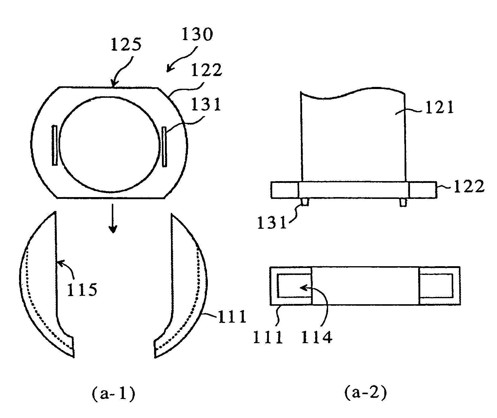
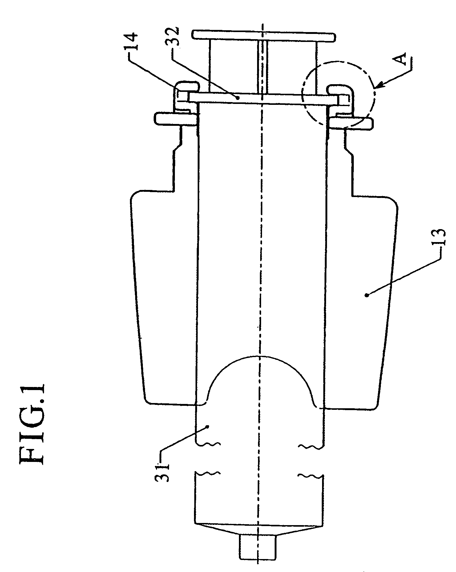
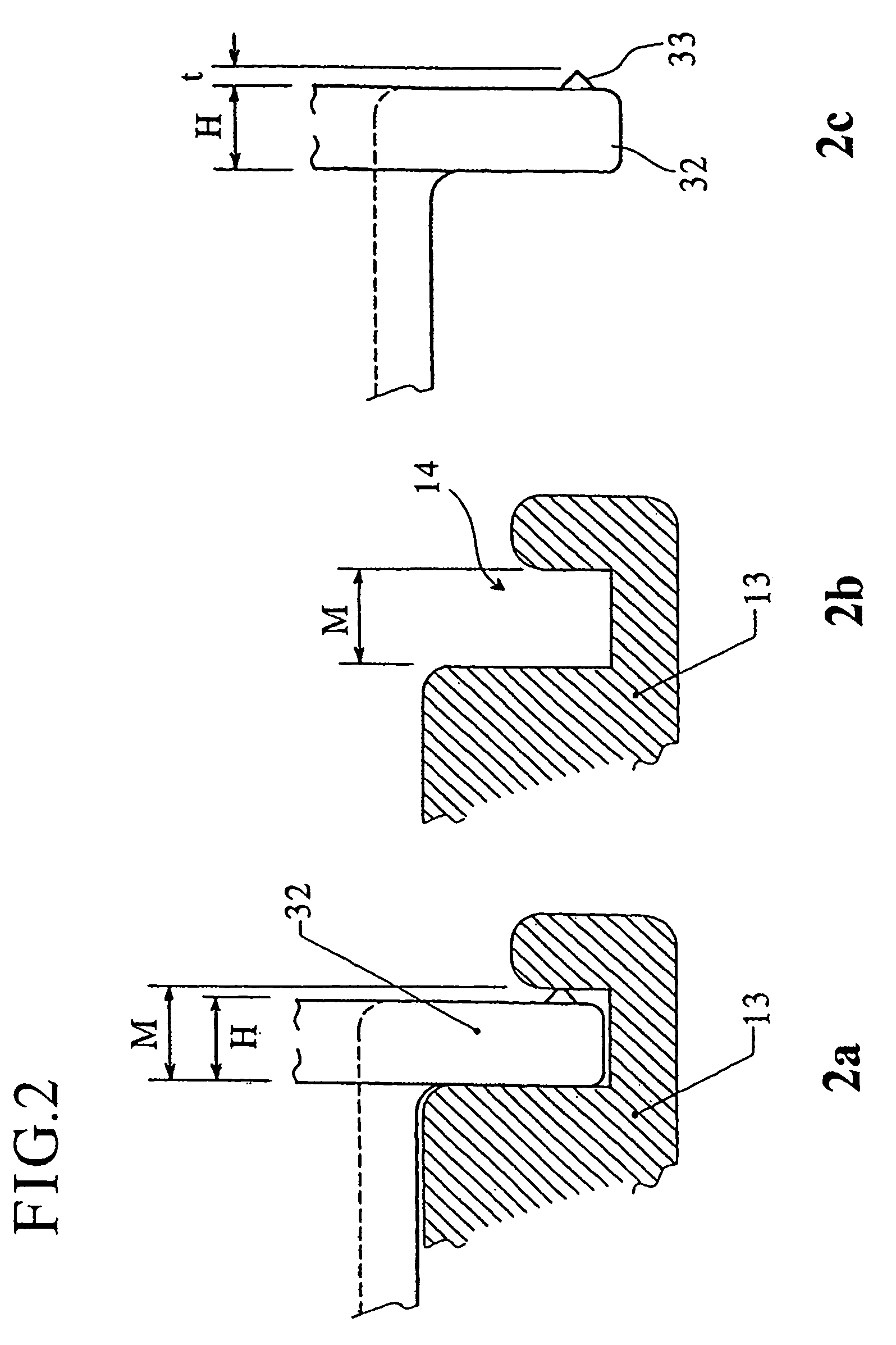
The present invention aims to prevent breakage of syringe barrels during injection of high viscosity substances. The invention provides an improved syringe barrel that is resistant to breakage, even when used with a usual type of syringe. The invention also provides a cylinder holder that does not cause breakage of the syringe barrel, even when used with an improved syringe barrel. The invention further provides a guide that can restrict the mounting direction of the syringe barrel and prevent rotation of the cylinder holder when the syringe barrel is mounted on the cylinder holder. The invention also includes various improvements to the flange of the syringe barrel, such as a concave portion, a guide, and a reinforcing rib. The invention can be used in pre-filled syringes filled with chemical solutions, such as contrast agents. The automatic injecting apparatus described in the patent text can be used with the present invention.

Problems solved by technology

Injection of a chemical solution having high viscosity such as a contrast agent for X ray CT imaging and a contrast agent for MRI (magnetic resonance imaging apparatus) requires high pressure, causes difficulty in manual handling, and makes intense jobs.
The reason for this design is also that if the clearance is designed to zero completely, mounting may be sometimes impossible due to certain extent production error to be taken into consideration because the syringe barrel and the cylinder holder (including the adaptor) are usually formed of different materials.
Consequently, slight backlash and play in mounted condition is inevitable.
However, if there is an error in the mounting procedure, the syringe may sometimes be raised from the right position.
Therefore, during diagnosis, since the automatic injecting apparatus is occupied, sucking of a chemical solution is impossible.
However, a syringe of generally spread type as shown in FIG. 11 and the like has a merit that a chemical solution is filled in the syringe and is prepared previously as a chemical solution for the next inspection, even in diagnosis, since suction of a chemical solution is possible even manually and consequently an automatic injecting apparatus is not necessarily occupied.
As described above, there have been made various improvements in syringes for injecting a chemical solution such as a contrast agent and the like, however, when a chemical solution having high viscosity such as a contrast agent is injected, strong force is applied to a flange, consequently, the syringe may occasionally be broken if there are a small number of flange surfaces receiving pressure.

Method used


Image

  • Syringe barrel with guide
  • Syringe barrel with guide
  • Syringe barrel with guide

Examples


examples

[0191]The following examples illustrate the present invention further in detail below.

[0192]In producing a mold for production of a cylinder holder holding a 100 mL syringe barrel, the mold surface of a part which forms the front surface of a cylinder holder was roughened by a sand blast method. By this mold, a cylinder holder was produced according to injection molding using a polycarbonate resin. The surface roughness of the front surface of a flange insertion groove was No. 100 (Example 1), No. 200 (Example 2) or No. 300 (Example 3) in terms of count of sand paper (#100, #200 and #300, respectively).

[0193]By using this cylinder holder, a 23 G butterfly needle was mounted on a syringe (internal diameter: 32 mm) of 100 mL capacity using a usual polypropylene syringe barrel in which the surface of a flange had not been roughened, and a pressure-resistance test was conducted using water as injection liquid. The results are shown in Table 1. In this test, breakage of the syringe and d...


PUM


Abstract

Since this syringe has projections provided on the rear surface of a flange of a syringe barrel, when it is inserted in an insertion groove of a cylinder holder, the tips of projections are compressed and the flange is fixed. Consequently, even when a solution having high viscosity is injected at higher pressure, breakage does not occur easily. Further, pressure-receiving area may also be increased by providing a guide defining mounting direction of a syringe, alternatively, a positioning mechanism may be provided so as to obtain mounting at a correct position, or the surface of a flange may be roughened.

Description

RELATED APPLICATIONS[0001]This application is a divisional of U.S. patent application Ser. No. 09 / 780,73 1, filed Feb. 9, 2001, now U.S. Pat. No. 6,676,635, which claims priority to the following prior foreign applications: Japanese Patent Application No. 2000-033520, filed Feb. 10, 2000; Japanese Patent Application No. 2000-037176, filed Feb. 15, 2000; Japanese Patent Application No. 2000-198358 filed Jun. 30, 2000; and Japanese Patent Application No. 2001-026782 filed Feb. 2, 2001.BACKGROUND OF THE INVENTION[0002]1. Field of the Invention[0003]The present invention relates to a syringe barrel suitable for injection at high injection pressure using a driving mechanism such as an automatic injector and the like; a cylinder holder used for a syringe driving mechanism such as an automatic injecting apparatus and the like; syringe piston; and piston holder.[0004]2. Description of the Related Art[0005]Syringes are used for injection of liquid in various fields typically including a medi...

Claims


Application Information

Patent Timeline
Patent Type & Authority Patents(United States)
IPC IPC(8): A61M37/00A61M5/00A61M5/145A61M5/28A61M5/31B05C5/00B05C13/02
CPCA61M5/007A61M5/14546A61M5/1456A61M5/1458A61M5/3135A61M2205/14A61M5/31
Inventor NEMOTO, SHIGERU
Owner NEMOTO KYORINDO KK
Learn More