Radar level gauge using elliptically or circularly polarized waves

a technology of elliptical or circular polarization and radar level gauge, applied in the direction of radio wave reradiation/reflection, measurement devices, instruments, etc., can solve the problem that in any case, unwanted power coupling may be neglected

Inactive Publication Date: 2007-09-04
ROSEMOUNT TANK RADAR
View PDF3 Cites 34 Cited by
  • Summary
  • Abstract
  • Description
  • Claims
  • Application Information

AI Technical Summary

Benefits of technology

[0010]It is therefore an object of the present invention to provide an improved radar lev...

Problems solved by technology

In practical realizations the two propagation modes need not be orthogonal i...

Method used


Image

  • Radar level gauge using elliptically or circularly polarized waves
  • Radar level gauge using elliptically or circularly polarized waves
  • Radar level gauge using elliptically or circularly polarized waves

Examples


first embodiment

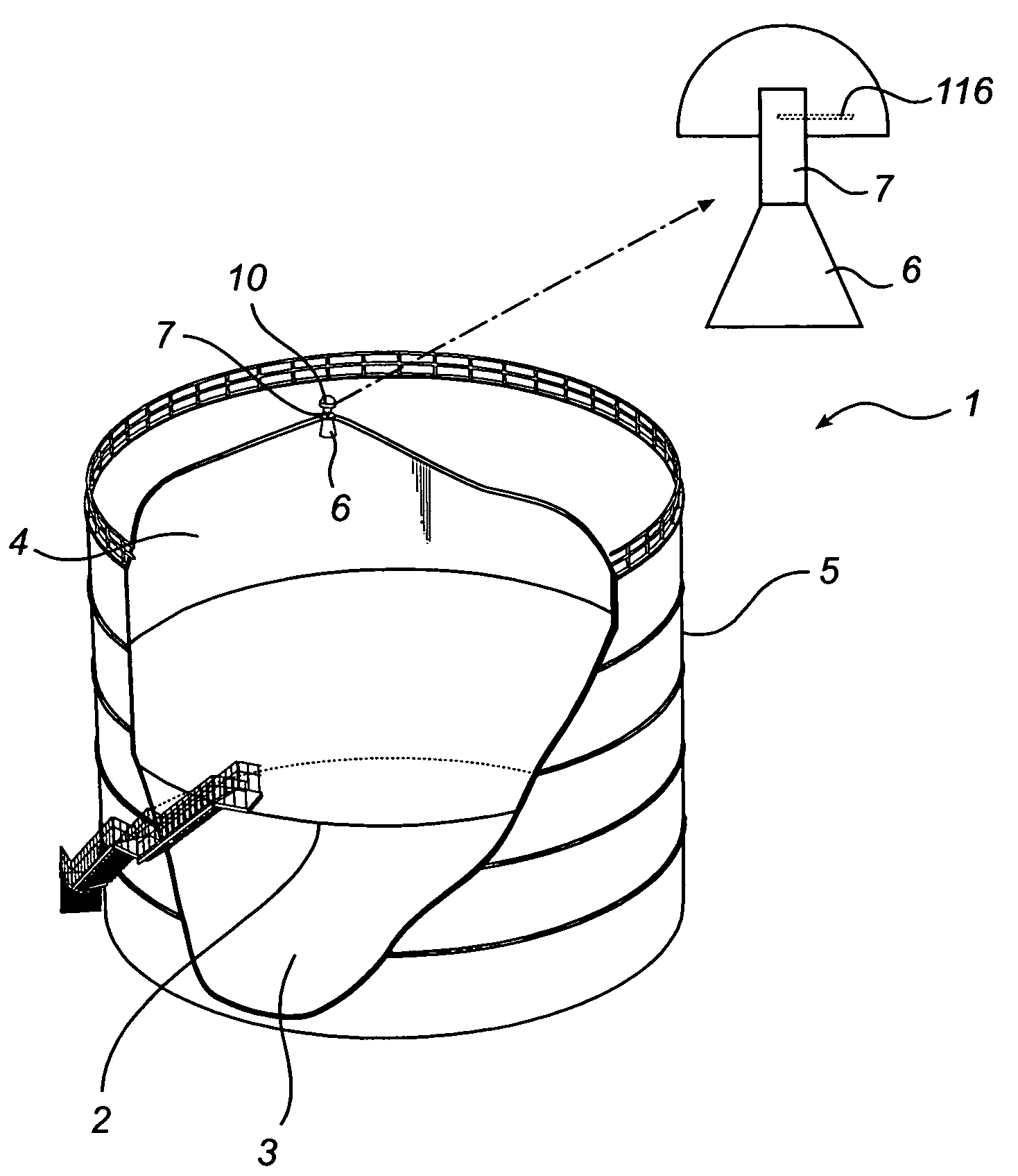
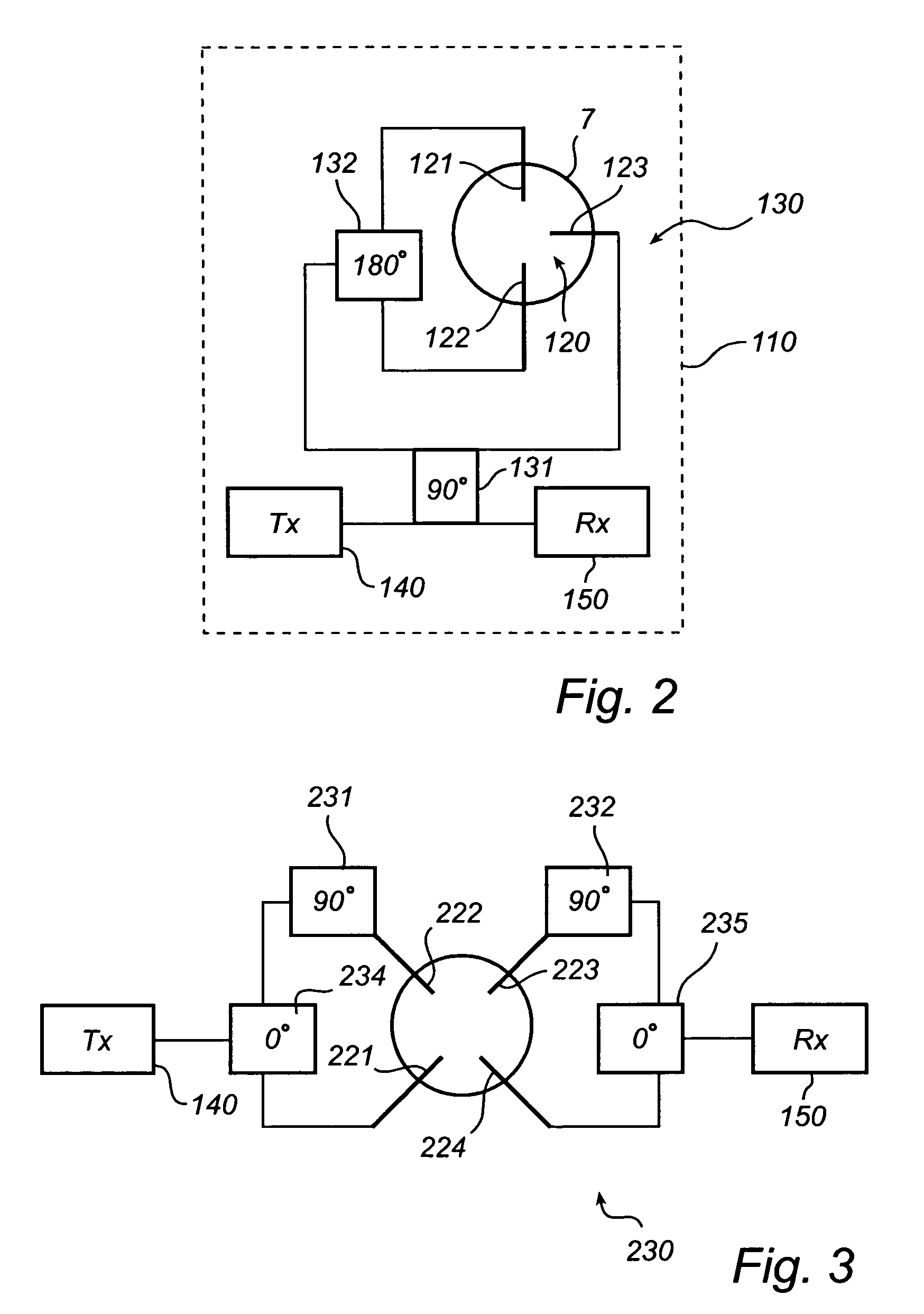
[0039] as is illustrated in FIG. 2, the entire microwave circuit arrangement is arranged on a single printed circuit board (PCB) 110. The microwave circuit arrangement comprises feeding probes 120, to be arranged in the waveguide 7 or the antenna 6, a microwave generating unit 140, or a corresponding microwave input port to be connected to a microwave generating unit, a microwave receiving unit 150, or a corresponding output port to be connected to a microwave receiving unit, and a coupling circuitry 130 for transferring and feeding signals between the microwave generating unit and the feeding probes, and between the microwave receiving unit and the feeding probes, respectively.

[0040]The microwave generating unit 140, generally referred to as transmitting unit (TX), is adapted to generate a microwave signal to be used for pulsed radar level measurement or FMCW, as is per se well known in the art. The microwave generating unit 140 may be implemented on the PCB 110. However, as an alt...

second embodiment

[0050]Further, the coupling circuit 230 comprises a 0 degree couplers 234, 235 connected to the output of the TX 140 and the input of the RX 150, respectively. The 0 degree couplers are commonly known as dividers, and e.g. 0 degree Wilkinson power dividers may be used. The divider 234 connected to the TX 140 is connected to the transmitting feeding probes 231, 232. However, one of the divided signal parts is provided through a 90 degree phase delay 231 so that the signals provided to the transmitting feeding probes are correspondingly phase separated. The 90 degree phase delay may e.g. be realized by means of a 90 degree coupler, as discussed in the foregoing. However, preferably the 90 degree phase delay is realized with 90 degrees Schiffman phase shifters, giving a more wide-band phase-shift. Similarly, the divider 235 connected to the RX 150 receives signals from the receiving feeding probes 233, 234. However, one of the received signal parts is provided through a 90 degree phas...

third embodiment

[0054]Further, the coupling circuit 330 comprises a 0 degree couplers 334, 335 connected to the output of the TX 140 and the input of the RX 150, respectively. For example, 0 degree Wilkinson power dividers may be used. The dividers 334, 335 are each connected to a 90 degree coupler 331, 332. The 90 degree phase delay may e.g. be realized by means of a 90 degree coupler, as discussed in the foregoing. The 90 degree couplers are each connected to two feeding probes 321, 322 and 323, 324, respectively, in order to provide phase differentiated signals to / from said feeding probes. Further, the dividers 334, 335 are each connected to a common crossing 336 (marked X-ing), which may e.g. be realized by means of two by two 90 degrees hybrid couplers or by a more conventional line crossing. The crossing 336 is further connected to each of the 90 degree couplers 331 and 332. With this type of crossing it is still possible to keep the pattern on the PCB within one single layer, whereby an ine...


PUM


Abstract

A radar level gauge (RLG) is provided for determining a filling level of a filling material contained in a container by transmitting and receiving elliptically or circularly polarized waves. The RLG comprises: a feeding circuitry for feeding and receiving two essentially orthogonal elliptically polarized waveguide modes, one of the modes for transmission and another mode for reception; an antenna for transmitting the waveguide modes towards the filling material and for receiving reflected signals; and a waveguide to provide signals between said feeding circuitry and the antenna. Further, the feeding circuitry comprises: a microwave generating unit (TX); a microwave receiving unit (RX); at least three feeding probes being at least partly exposed to the interior of the waveguide; and a coupling circuitry for transferring and feeding signals between each feeding probe and the microwave generating unit and/or the microwave receiving unit. At least the coupling circuitry and the feeding probes are implemented on a common printed circuit board (PCB), and the printed circuit board is arranged transversely over the waveguide.

Description

FIELD OF THE INVENTION[0001]The present invention relates to a radar level gauge for improved radar level gauging of a filling level of filling material in a vessel and in particular to a radar filling level measuring device capable of generating and receiving an elliptically polarized wave or, as a special case, a circularly polarized wave.BACKGROUND OF THE INVENTION[0002]Radar level gauges are commonly used for the continuous determination of filling levels of filling materials, such as liquids or bulk materials, in container, such as a tank or other vessels. In such measurement systems, the filling level is determined based on a delay or time difference between a signal transmitted towards the surface of the filling material, and a received signal reflected from said surface. For the determination of the desired wave delay, there are various radar principles. One of these is the impulse delay method (pulse radar method), another is the frequency modulated continuous wave (FMCW) r...

Claims


Application Information

Patent Timeline
IPC IPC(8): G01R27/04
CPCG01F23/284
Inventor PENNDAL, NIKLASJIRSKOG, ANDERSEDVARDSSON, OLOV
Owner ROSEMOUNT TANK RADAR
Why Eureka
Try Eureka