Noise removal using 180-degree or 360-degree phase shifting circuit

a phase shifting circuit and phase shifting technology, applied in the field ofnoise removal circuits, can solve problems such as recording or reproduction failure and other problems, wobble signal is impossible to read correctly, clock jitter,

Active Publication Date: 2007-09-04
SEMICON COMPONENTS IND LLC
View PDF5 Cites 9 Cited by
  • Summary
  • Abstract
  • Description
  • Claims
  • Application Information

AI Technical Summary

Benefits of technology

[0042]The input signal may be a wobble signal for rotation control detected from optical disk's recording track. This reduces noise component in the wobble signal, preventing occurrence of jitter during optical disk recording and reproduction. As a result, problems derived from noise in the wobble signal can be resolved such as failure to achieve synchronization between optical disk rotation speed and clock, thus allowing proper recording and reproduction.

Problems solved by technology

Jitter occurs in the clock during optical disk recording or reproduction in the event of an increase in this noise component.
Occurrence of the jitter has hindered synchronization of the optical disk rotation speed and the clock, resulting in recording or reproduction failure and other problems.
The wobble signal may become amplitude-modulated depending on the disk or pickup condition, occasionally resulting in the wobble signal being impossible to read correctly.
Further, the wobble signal may be lost as a result of disk damage or other cause, occasionally adversely affecting the control system using the wobble signal.
Still further, an AC signal may be superposed onto the wobble signal at disk rotation cycles due to effects such as unevenness or double refraction in disk protective film and pickup condition, occasionally resulting in the wobble signal being difficult to read correctly.

Method used


Image

  • Noise removal using 180-degree or 360-degree phase shifting circuit
  • Noise removal using 180-degree or 360-degree phase shifting circuit
  • Noise removal using 180-degree or 360-degree phase shifting circuit

Examples


first embodiment

SECOND VARIANT OF FIRST EMBODIMENT

[0061]The second variant of the first embodiment shown in FIG. 1 will be described with reference to FIG. 6. In the second variant, a PLL (phase-locked loop)-based phase-adjusting circuit is employed as the noise removal circuit shown in FIG. 1 to achieve synchronization with the input signal I. That is, a VCO circuit (synchronizing signal output section) is added to the first variant of FIG. 3 discussed earlier. The second variant will be described, focusing on the differences from the first variant shown in FIG. 3. The output of the phase comparator (synchronizing signal output section) shown in FIG. 5 is input to the frequency-controlled phase shifting circuit shown in FIG. 4 and to the VCO circuit as a frequency control signal that serves as a synchronizing signal. The output of the VCO circuit is fed back and input to the phase comparator (input 2). It should be noted that high-frequency noise in the phase comparator output is removed by the ca...

second embodiment

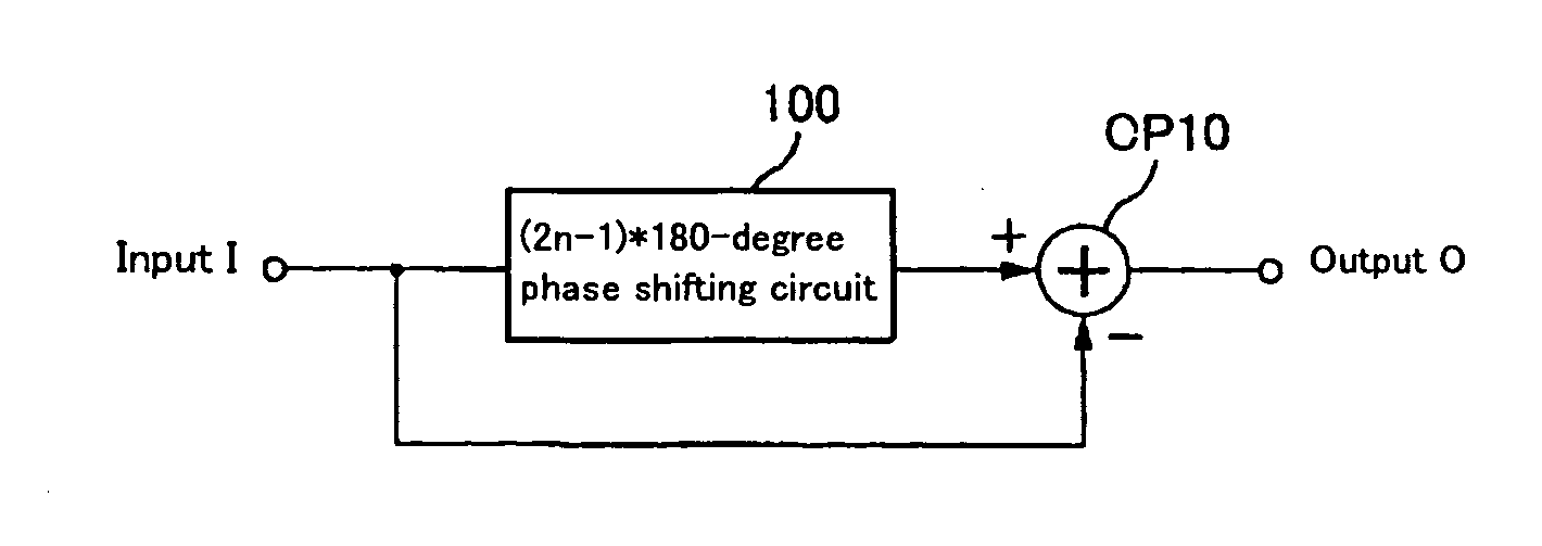
[0066]The second embodiment will be described with reference to FIGS. 8 and 9. First, a signal phase-shifted from the signal component of the input signal I by n*360 degrees (hereinafter referred to as a “360-degree shifted signal”) is generated by a n*360-degree phase shifting circuit (360-degree shifting section) 200 and output to one of the non-inverted input terminals (+) of an operational amplifier (sum output section) OP20, as shown in the block diagram of FIG. 8 showing the principle of noise removal. It should be noted that “n” is an integer. The input signal I is input to the other non-inverted input terminal (+) of the operational amplifier OP20. Therefore, an output O of the operational amplifier OP20 is the sum of the input signal I and the 360-degree shifted signal. The noise removal circuit for the input signal I is thus configured.

[0067]FIG. 9 shows a specific circuit configuration of the phase shifting circuit shown in. FIG. 8. That is, a stage consisting of an opera...

third embodiment

[0073]The third embodiment will be described with reference to FIG. 10. This embodiment is, as shown in FIG. 10 showing the principle of noise removal, the result of combination of the first embodiment shown in FIGS. 1 to 7 and the second embodiment shown in FIGS. 8 and 9. The combination produces a synergetic effect.

[0074]That is, the (2n−1)*180-degree phase shifting circuit 100 generates a signal phase-shifted by (2n−1)*180 degrees from the signal component of the input signal I (hereinafter referred to as “180-degree shifted signal”) and outputs the signal to the inverted input terminal (−) of an operational amplifier (calculation output section) OP30. It should be noted that “n” is an integer.

[0075]Further, a signal phase-shifted from the signal component of the input signal I by n*360 degrees (hereinafter referred to as “360-degree shifted signal”) is generated by the n*360-degree phase shifting circuit 200 and output to the non-inverted input terminal (+) of the operational am...


PUM

PropertyMeasurementUnit
phaseaaaaaaaaaa
polarityaaaaaaaaaa
rotationaaaaaaaaaa

Abstract

A noise removal circuit of the present invention comprises a 180-degree odd multiple shifting section for outputting a 180-degree shifted signal that is phase-shifted from an input signal by an odd multiple of 180 degrees and difference output section for outputting a difference between the input signal and the 180-degree shifted signal. The noise removal circuit comprises a 360-degree shifting section for outputting a 360-degree shifted signal that is phase-shifted from an input signal by an integral multiple of 360 degrees and sum output section for outputting a sum of the input signal and the 360-degree shifted signal.

Description

CROSS-REFERENCE TO RELATED APPLICATIONS[0001]The present application claims priority upon Japanese Patent Application No. 2002-349363 filed on Dec. 2, 2002, which is herein incorporated by reference.BACKGROUND OF THE INVENTION[0002]1. Field of the Invention[0003]The present invention relates to a noise removal circuit and a noise removal method.[0004]2. Description of the Related Art[0005]Prior art related to signal noise removal are covered in signal recording and reproduction devices such as a hard disk and an optical disk. For instance, optical disks that allow data recording using laser beam are classified into write-once optical disks such as CD-R, DVD-R and DVD+R and rewritable optical disks such as CD-RW, MD, DVD-RAM, DVD-RW, DVD+RW and MO.[0006]A recording and reproduction device for such optical disks (hereinafter written as an “optical disk device”) comprises, as an example, an optical pickup, a WBL (wobble signal) detection unit, an LPP detection unit, a write clock gener...

Claims


Application Information

Patent Timeline
Patent Type & Authority Patents(United States)
IPC IPC(8): G11B7/00H03K19/094H04B1/10G11B20/14G11B7/005G11B20/10G11B20/24
CPCG11B20/24G11B7/0053G11B7/005
Inventor KURIHARA, SHINJI
Owner SEMICON COMPONENTS IND LLC
Why Eureka
Try Eureka