Digital compensation for optical transmission system

a digital compensation and optical transmission technology, applied in transmission, electromagnetic transmission, electrical equipment, etc., can solve the problems of limiting the cost/performance trade-off, many complex solutions have been tried to compensate for pmd and cd with limited success, and limiting the success of both coherent and direct detection systems in high-capacity systems. to achieve the effect of increasing the chance of successful and sufficiently rapid convergence, and taking into account non-adjustable effects more readily

Active Publication Date: 2007-09-04
CIENA
View PDF4 Cites 86 Cited by
  • Summary
  • Abstract
  • Description
  • Claims
  • Application Information

AI Technical Summary

Benefits of technology

[0007]The use of such digital adaptive equalizing can be more efficient or more cost effective than optical domain methods of trying to compensate for impairments such as chromatic dispersion and PMD. Furthermore, it can also reduce the problems which have so far held back coherent optical detection from widespread implementation, such as polarization alignment and phase tracking associated with the local oscillator in the receiver. This could be commercially significant if it enables the upgrade of existing installed transmission routes to increase capacity without the huge expense of replacing the old, relatively poor quality fiber. The optical receiver need not necessarily generate digital outputs directly, it can be arranged in stages, separating the polarizations and phases in the optical domain, followed by conversion into the electrical domain, followed by analog to digital conversion. The term diverse is defined as meaning the output of the optical receiver retains all of the phase and polarization information in the input optical signal.
[0009]An additional feature of some embodiments is the optical receiver having four outputs, composed of the in-phase and quadrature waveforms on two polarizations. This is an optimal way of providing a complete mapping of the optical field of the optical input signal into the electrical domain. This retains information which is lost by receivers using direct detection of the optical signal.
[0010]An additional feature of some embodiments is the optical signal having two or more information channels modulated orthogonally, the adaptive equalizer being arranged to maximise the orthogonality of the information channels.
[0013]An additional feature of some embodiments is the transversal filter being adapted by iteration of a limited set of independent variables including three defining the orientation and magnitude of PMD, and one each for the chromatic dispersion, the orientation of the polarizing element at the receiver, and the phase of a local oscillator used for phase diverse detection in the optical receiver. Minimising the number of independent variables, to be fewer than the number of taps in the transversal filters, can increase the chances of successful and sufficiently rapid convergence on a true global minimum.
[0016]An additional feature of some embodiments is the adaptive equalizer having fractional spacing corresponding to sampling at an integer multiple of the bit rate. This can improve performance, but at the cost of requiring higher speed electronics.
[0022]Another aspect provides a method of offering a data transmission service over the network. The advantages of the invention can enable improvements to be made in the system or network performance such as being more reliable or more flexible, having a greater capacity, or being more cost effective. Consequently data transmission services over the network can be enhanced, and the value of such services can increase. Such increased value over the life of the system, could prove far greater than the sales value of the equipment.

Problems solved by technology

In contrast coherent receivers require careful polarization alignment and phase tracking, which is difficult and can limit the cost / performance trade off.
Both coherent and direct detection systems are also limited in high capacity systems by distortions introduced by the optical path, mostly optical fiber.
Many complex solutions have been tried to compensate for PMD and CD with limited success.
Solutions which correct the distortion in the optical domain involve expensive optical components.
However, any such compensator will have a limited performance since in conventional direct detection systems, the optical field is not fully recovered, for example the phase and polarization information is lost.

Method used


Image

  • Digital compensation for optical transmission system
  • Digital compensation for optical transmission system
  • Digital compensation for optical transmission system

Examples


Embodiment Construction

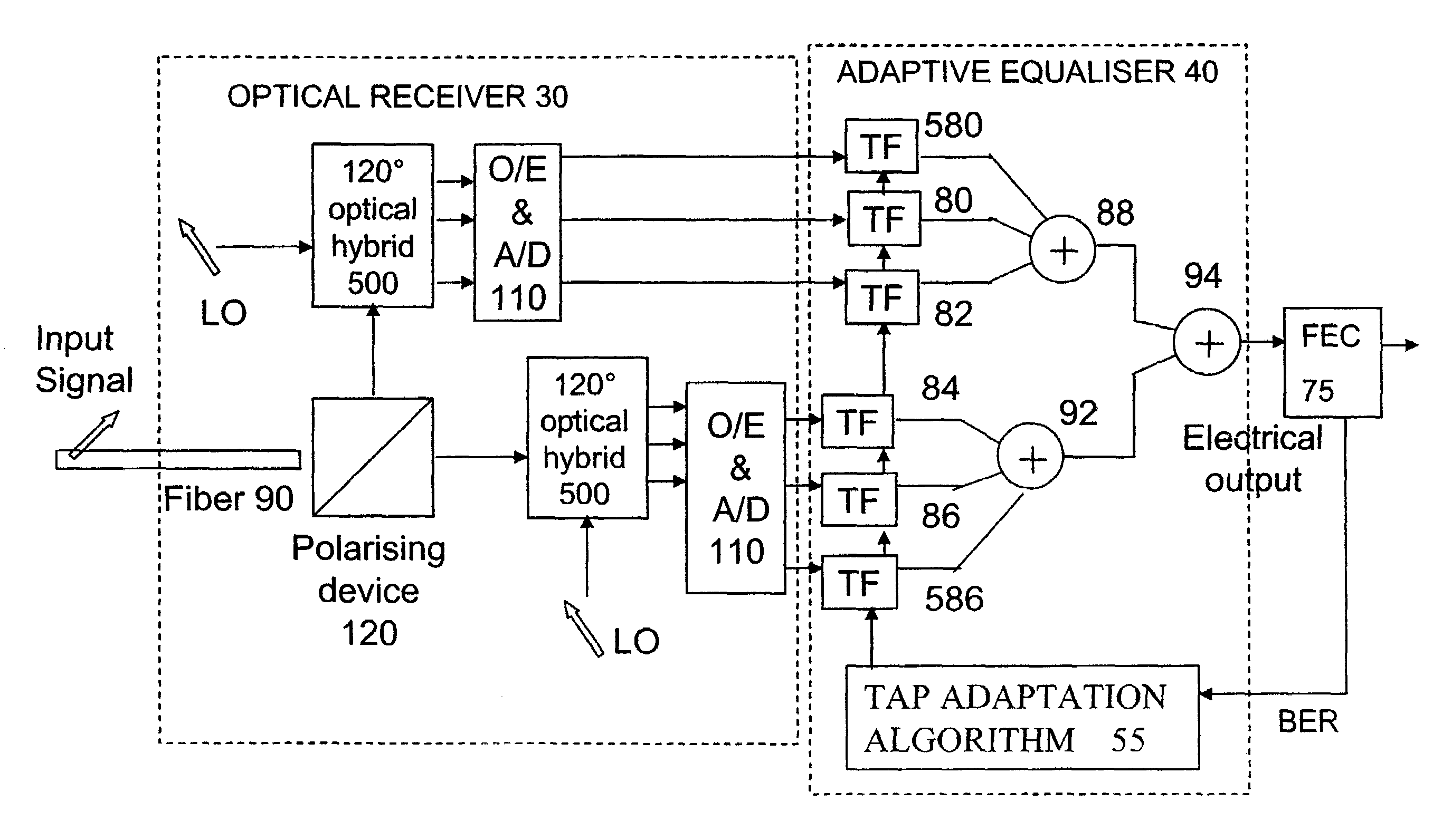
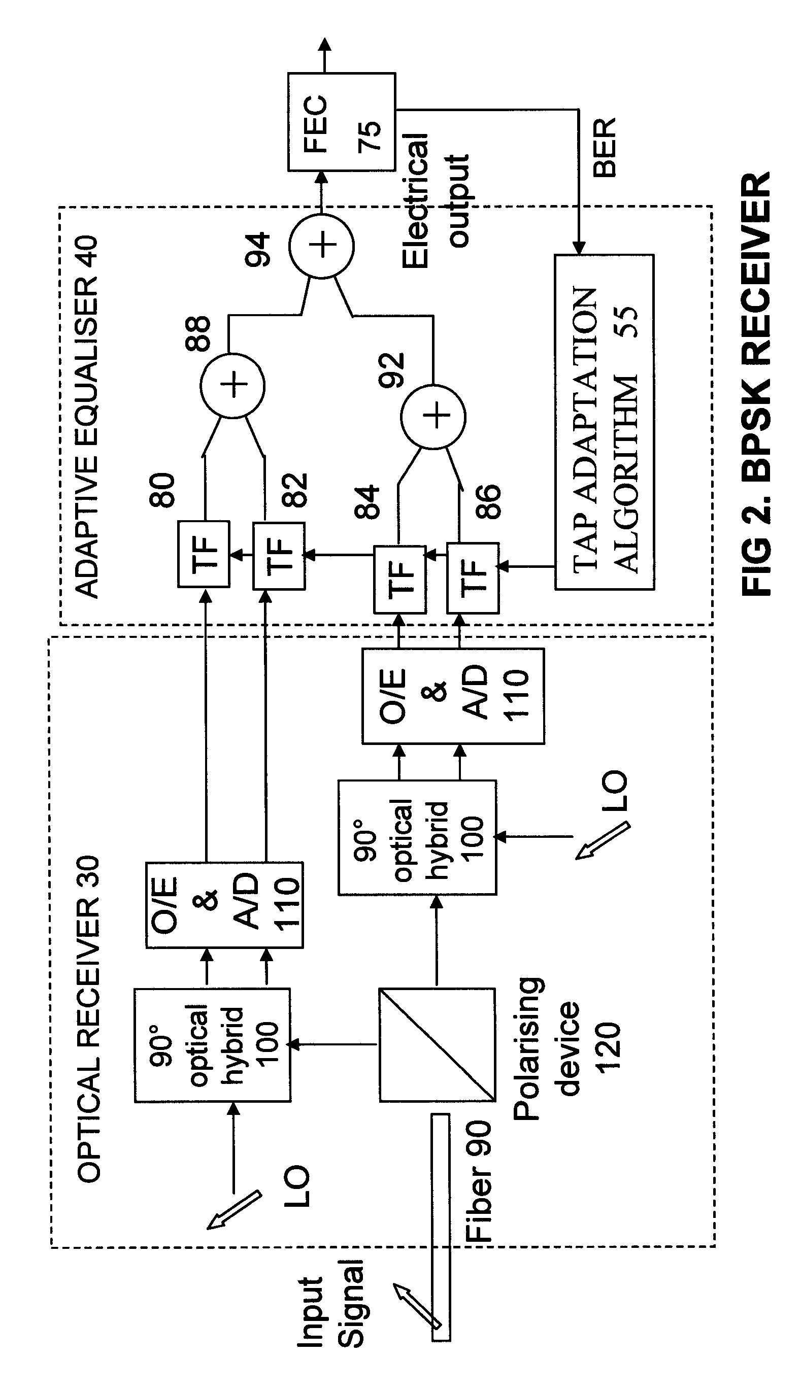
[0030]Adaptive equalization is a technique known for compensating for channel distorting effects in transmission systems, using digital filters, e.g. transversal filters, maximum likelihood sequence estimators, or maximum a posteriori detectors. What is notable is the application of this with a coherent optical detector to compensate for optical distortions. Embodiments of the invention use coherent detection of an incoming optical signal to map the optical field into four electrical signals. A subsequent digital adaptive equalizer can use these signals, containing phase and polarization information, for compensation of effects such as polarization mode dispersion (PMD) and chromatic dispersion which otherwise cause an increase in the bit error rate.

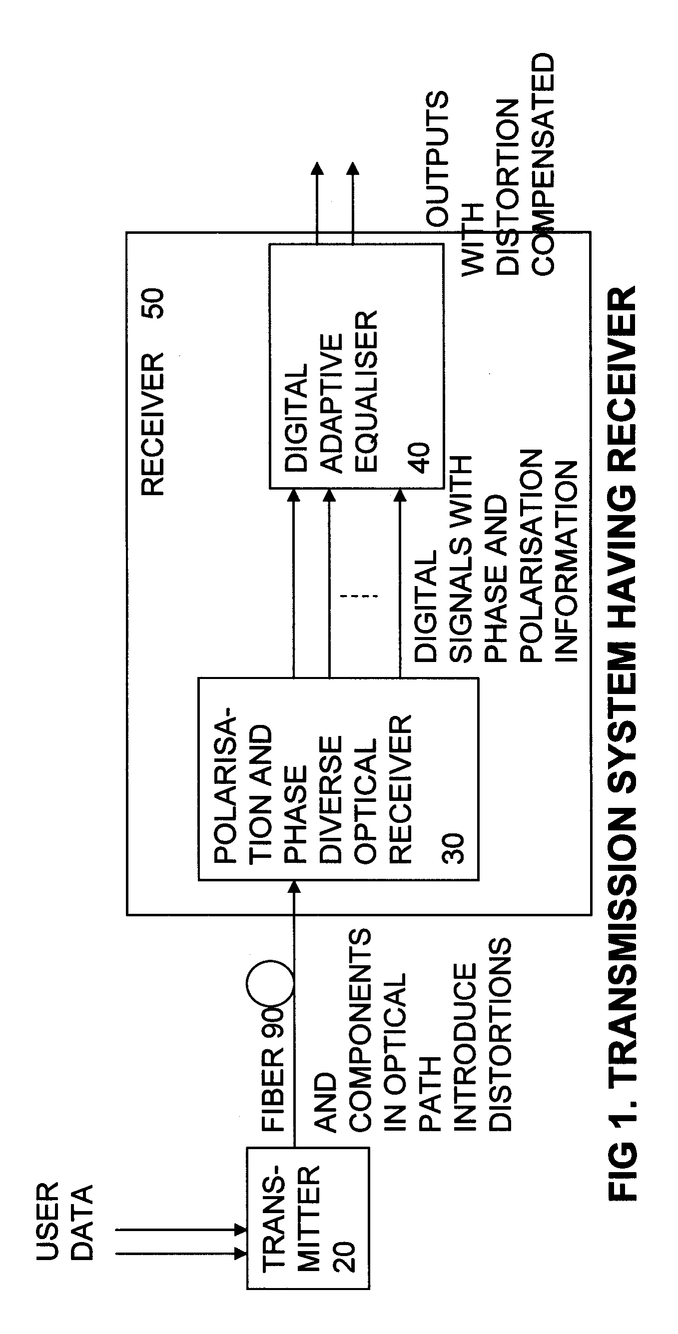
[0031]FIG. 1 shows an optical transmission system using an embodiment of the invention. A transmitter 20 is shown for modulating user data onto an optical signal. This is fed along an optical path including a fiber 90, typically many kil...


PUM


Abstract

A receiver for an optical transmission system, has a polarization diverse and phase diverse coherent optical receiver, and a digital adaptive equalizer for compensating for distortions in the optical signal introduced by the optical path. The entire field of the optical signal is mapped including phase and polarization information, to enable more complete compensation for impairments such as chromatic dispersion and PMD. Furthermore, it can also reduce the problems which have so far held back coherent optical detection from widespread implementation, such as polarization alignment and phase tracking. This can be applied to upgrade existing installed transmission routes to increase capacity without the expense of replacing the old fiber.

Description

FIELD OF THE INVENTION[0001]This invention relates to receivers for optical transmission systems, to digital adaptive equalizers for such receivers, to software for such equalizers, and to methods of offering a transmission service over such apparatus.BACKGROUND TO THE INVENTION[0002]Known optical transmission systems can be broadly categorized as direct detection, or coherent detection systems. In direct detection systems, at the receiver, the signal power is measured and therefore any phase and polarization information in the optical signal is ignored and lost. In coherent detection systems, the phase and / or polarization information is detected which enables the use of polarization and / or phase modulation as well as amplitude modulation, and so much greater information carrying capacity is possible, than in direct detection systems for a given optical signal to noise ratio. Direct detection systems have nevertheless dominated the market for long haul transmission systems due to th...

Claims


Application Information

Patent Timeline
Patent Type & Authority Patents(United States)
IPC IPC(8): H04B10/148
CPCH04B10/61H04B10/611H04B10/613H04B10/614H04B10/6161H04B10/6162H04B10/6166H04B10/65
Inventor SAVORY, SEB JWHITEAWAY, JAMES
Owner CIENA
Why Eureka
Try Eureka