Connector for inverter

a technology for connecting wires and inverters, which is applied in the direction of threaded fasteners, dc-ac conversion without reversal, coupling device connections, etc., can solve the problems of large space required for wire distribution, inevitably bulky wire proportions toward each motor, etc., and achieve the effect of increasing the width or bulk of the inverter connectors

Inactive Publication Date: 2007-09-11
AUTONETWORKS TECH LTD +2
View PDF3 Cites 23 Cited by
  • Summary
  • Abstract
  • Description
  • Claims
  • Application Information

AI Technical Summary

Benefits of technology

[0008]However, a thick wire must be employed as the wires 4 because a large current capacity is required, and in the case of employing a shielded wire the wires 4 become thicker still. Accordingly, since such wires are difficult to bend, a portion of the wire which is bent toward each motor inevitably becomes bulky. Further, since two wires disposed side by side in each pair of wires 4 must be rearranged to constitute a group according to the three phases, the wires form multi-level intersections, thereby making the bent portion still bulkier. Consequently, a large space is required for distribution of the wires 4.
[0011]According to the first aspect of the present invention, when the apparatus-side connector housing and the wire-side connector housing are fitted, the wires connected to the wire connection portion are already grouped so as to include the U, V and W phases for the respective loads, when led out of the wire-side connector housing. Such a configuration eliminates the need of bending the wires in a large radius when directing the wires toward the respective loads, thereby permitting distributing the wires to the respective loads in a smaller space.
[0012]According to the second aspect of the present invention, since the busbars are formed by molding so as to be integrally retained in the wire-side connector housing, the number of manufacturing processes can be reduced unlike a case of press-fitting the busbars into the wire-side connector housing, which results in improvement in productivity and reduction in manufacturing cost. Also, since the busbars and the wire-side connector housing are more firmly joined, a backlash or the like can be prevented.
[0013]According to the third aspect of the present invention, the terminal fitting portions provided in the apparatus-side connector housing are grouped so as to include the U, V and W phases for the respective loads. Therefore, once the apparatus-side connector housing is fitted to the wire-side connector housing, which may be attached to a terminal portion of the wires, the wires led out of the wire-side connector housing are already grouped so as to include the U, V and W phases for the respective loads. Such a configuration eliminates the need of bending the wires in a large radius when directing the wires toward the respective loads, thereby permitting distributing the wires to the respective loads in a smaller space.
[0014]According to the fourth aspect of the present invention, since the busbars are formed by molding so as to be integrally retained in the apparatus-side connector housing, the number of manufacturing processes can be reduced unlike a case of press-fitting the busbars into the apparatus-side connector housing, which results in improvement in productivity and reduction in manufacturing cost. Also, since the busbars and the apparatus-side connector housing are more firmly joined, a backlash or the like can be prevented.
[0016]When performing a molding process, the busbar may be deformed by an injection pressure to thereby make contact with another busbar. Widening a gap between busbars could be an option for preventing the busbars from contacting each other, however, this leads to an increase in width or bulk of the inverter connector. By contrast, according to the present invention, isolating the busbars with the separators securely prevents the busbars from contacting each other due to an injection pressure, and hence reducing a gap between the busbars, thus making it possible to miniaturize the inverter connector unit.

Problems solved by technology

Accordingly, since such wires are difficult to bend, a portion of the wire which is bent toward each motor inevitably becomes bulky.
Consequently, a large space is required for distribution of the wires 4.

Method used


Image

  • Connector for inverter
  • Connector for inverter
  • Connector for inverter

Examples


first embodiment

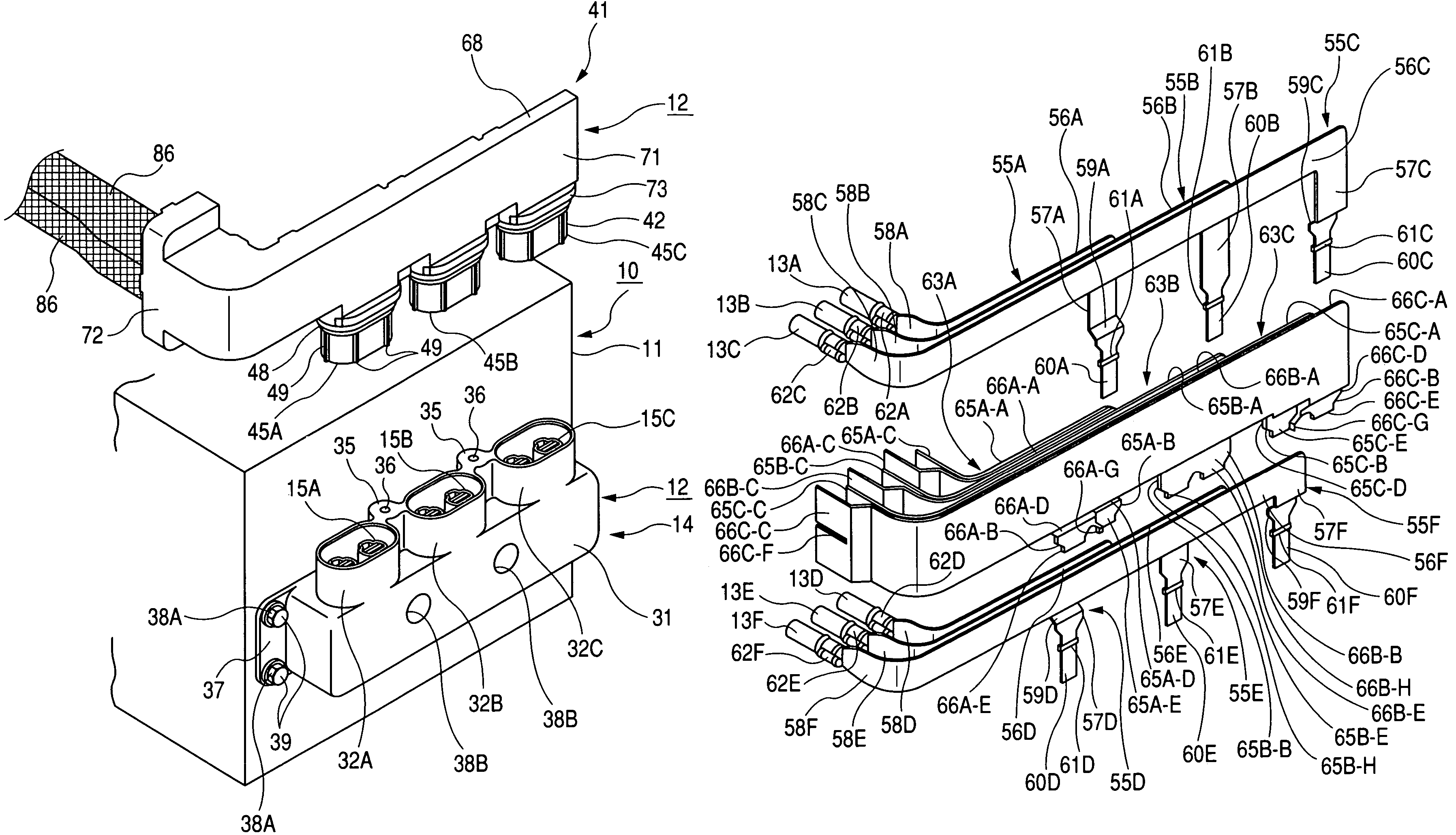
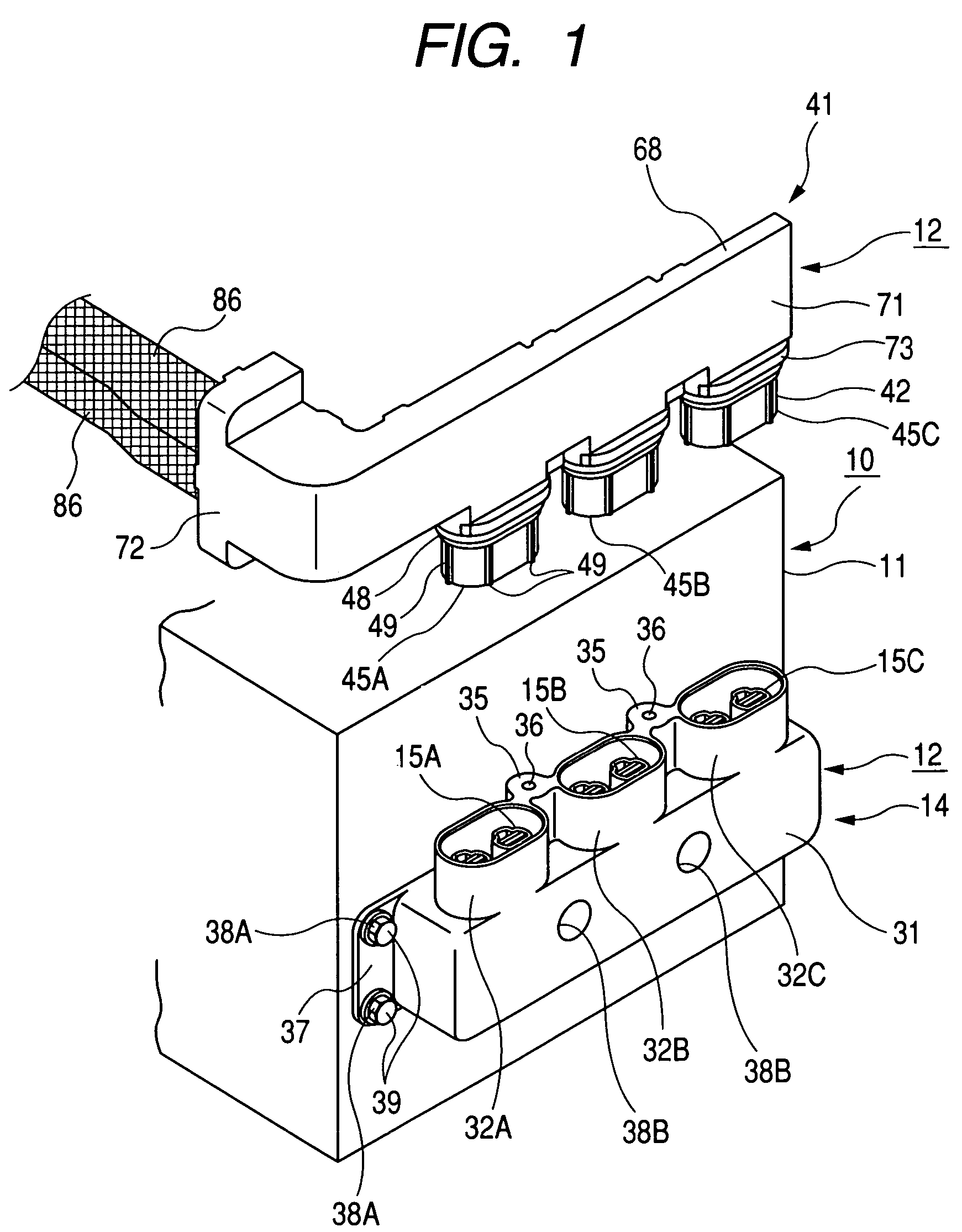
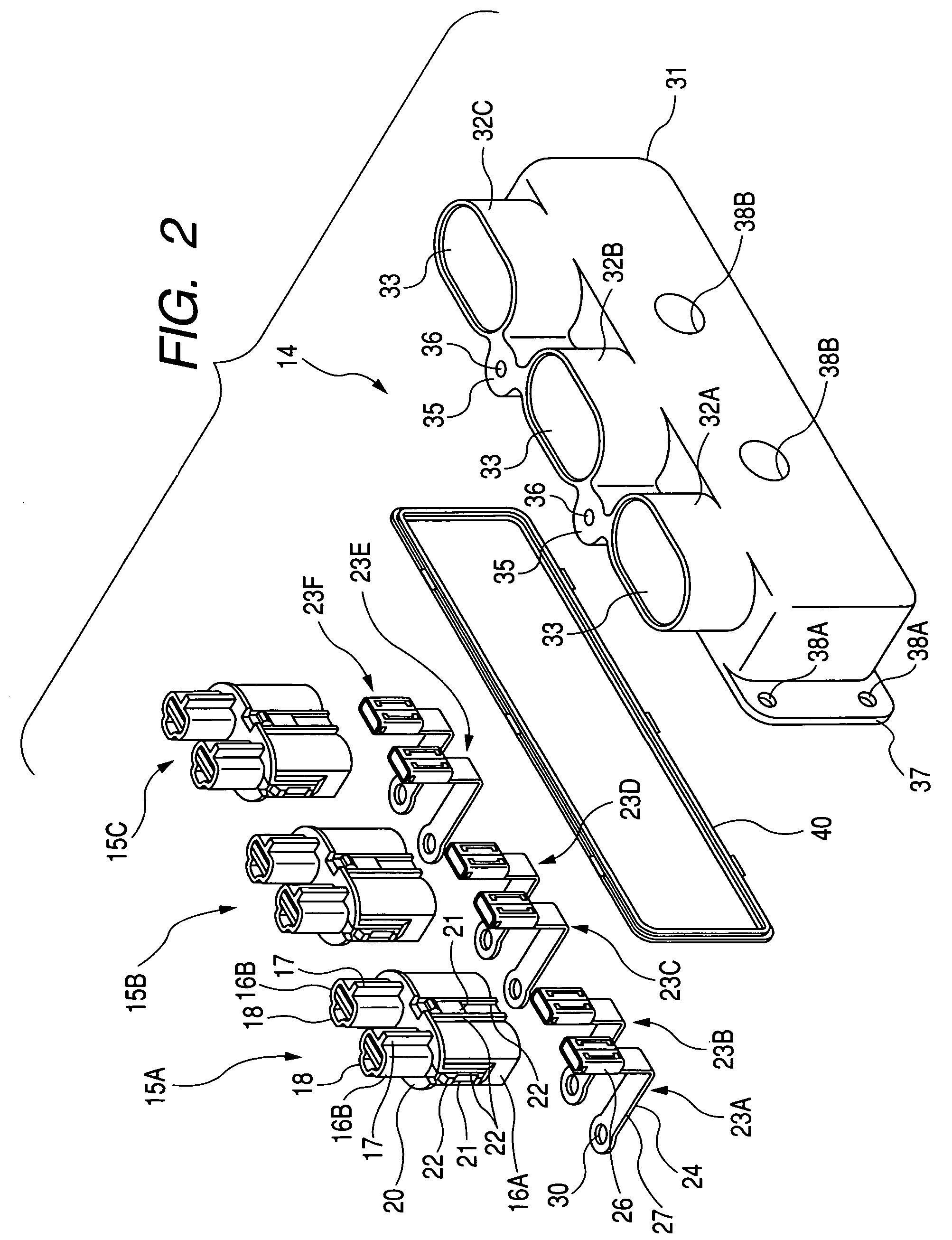
[0037]A first embodiment of the present invention will be described according to FIG. 1 to FIG. 10. Hereinafter, the right-hand side of FIG. 1 will be defined as a front or forward side, and the left-hand side thereof as a rear or backward side.

[0038][Inverter 10]

[0039]First, an inverter 10, to which an inverter connector 12 according to this embodiment is to be attached, will be described. The inverter 10 is constituted of an inverter main circuit (not shown) stored in a casing 11. The casing 11 is provided with a through hole (not shown) on a front face thereof for communication between inside and outside of the same. The casing 11 contains therein first to sixth output terminals arranged, a total of six output terminals (not shown), which are directly connected to the inverter main circuit (not shown) and aligned in a row in pairs respectively corresponding to U, V and W phases. The first and the second output terminals are output terminals of the U-phase; the third and the fourt...

second embodiment

[0123]A second embodiment of the present invention will be described according to FIG. 11 to FIG. 18. Hereinafter, the right-hand side of FIG. 11 will be defined as a front or forward side, and the left-hand side thereof as a rear or backward side.

[0124][Inverter 100]

[0125]First, an inverter 100, to which an inverter connector 104 according to this embodiment is to be attached, will be described. The inverter 100 is constituted of an inverter main circuit (not shown) stored in a casing 101. The casing 101 is provided with a through hole 103 on a front face thereof for communication between inside and outside of the same. The casing 101 contains therein a first to a sixth, a total of six output terminals (not shown), which are directly connected to the inverter main circuit (not shown) and aligned in a row in pairs respectively corresponding to U, V and W phases. The first and the second output terminals are terminals of the U-phase; the third and the fourth ones are of the V-phase; ...


PUM

PropertyMeasurementUnit
conductiveaaaaaaaaaa
insulatingaaaaaaaaaa
radiusaaaaaaaaaa

Abstract

A connector includes an apparatus-side connector housing attached to a casing of an inverter. The apparatus side-connector housing has a plurality of busbars. Each of the busbars has on one end portion a terminal fitting portion where a mating connector of the apparatus-side connector housing is connected and on the other portion an inverter-side terminal portion where an output terminal of the inverter main circuit board is connected. The busbars are divided and arranged into groups respectively corresponding to the U, V and W phases with respect to the inverter-side terminal portion. The busbars are arranged into groups respectively including the U, V and W three-phases for connection to each of the three-phase loads, with respect to the terminal fitting portion. A wire connecting inverter with a plurality of there phase loads can be arranged with respect to each of three phase loads with small space.

Description

BACKGROUND OF THE INVENTION[0001]1. Field of the Invention[0002]The present invention relates to a connector for an inverter.[0003]2. Description of the Related Art[0004]In a hybrid vehicle in which a gasoline engine and a motor are used in combination as a power source, a single inverter 1 may be connected to two three-phase motors, one for starting the engine and the other for assisting a driving force. In this case the inverter 1 is provided with output terminals 1A including a total of 6 output terminals, i.e. U-phase, V-phase and W-phase output terminals corresponding to the respective motors. These output terminals 1A are usually aligned in a row such that in-phase output terminals are adjacently located, so as to simplify a structure of the inverter main circuit. For example, when two each of output terminals 1A for the respective phases of U, V and W are designated as U1, U2, V1, V2, W1 and W2, U1 and U2 are disposed next to each other, then V1 and V2 next to each other, and...

Claims


Application Information

Patent Timeline
Patent Type & Authority Patents(United States)
IPC IPC(8): H01B17/00H01R4/70H01R9/03H01R24/00H01R13/629H01R107/00H02M7/48
CPCH01R13/62905
Inventor MIYAZAKI, SHO
Owner AUTONETWORKS TECH LTD
Why Eureka
Try Eureka