Moving transmitter correlation interferometer geolocation

a transmitter correlation and interferometer technology, applied in direction finders, multi-channel direction-finding systems using radio waves, instruments, etc., can solve problems such as affecting correct ambiguity resolution, affecting the accuracy of the resolution of ambiguity, and difficult to achieve long baselines

Active Publication Date: 2007-09-11
BAE SYST INFORMATION & ELECTRONICS SYST INTERGRATION INC
View PDF7 Cites 40 Cited by
  • Summary
  • Abstract
  • Description
  • Claims
  • Application Information

AI Technical Summary

Benefits of technology

[0021]Accordingly, there is a need for a DF interferometer system for moving aircraft that has a minimum numb...

Problems solved by technology

Thus, the desire for accurate bearing measurements, requiring a long interferometer baseline, conflicts with the need for robust phase or AOA ambiguity resolution, which is easier to accomplish with a short baseline.
In addition, long baselines are difficult to achieve when the receiving apparatus is on an aircraft.
Additionally, vibration can distort the trend and hinder correct ambiguity resolution.
Observer attitude motion can cause large changes in the ambiguity integer, m. These changes are difficult to separate from translational motion relative to the emitter.
Another drawback to the phase tracking approach is that the number of lobes, i.e. potential solutions, is determined by the ratio of d/λ, where d is the baseline length and λ is the signal wavelength.
This approach has a limitation in that it cannot handle signals from arbitrarily polarized transmissions.
The use of the SBI phase difference to initially compute a slant range means this method will not initially converge faster than a more conventional SBI-only ...

Method used


Image

  • Moving transmitter correlation interferometer geolocation
  • Moving transmitter correlation interferometer geolocation
  • Moving transmitter correlation interferometer geolocation

Examples


Embodiment Construction

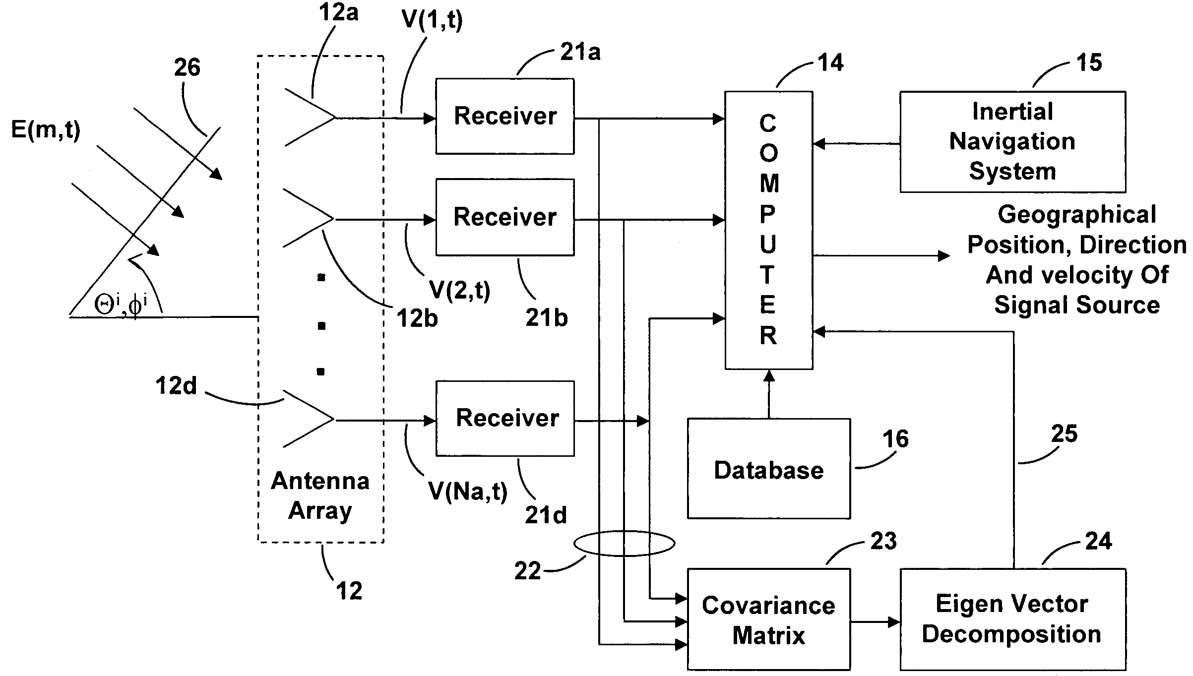
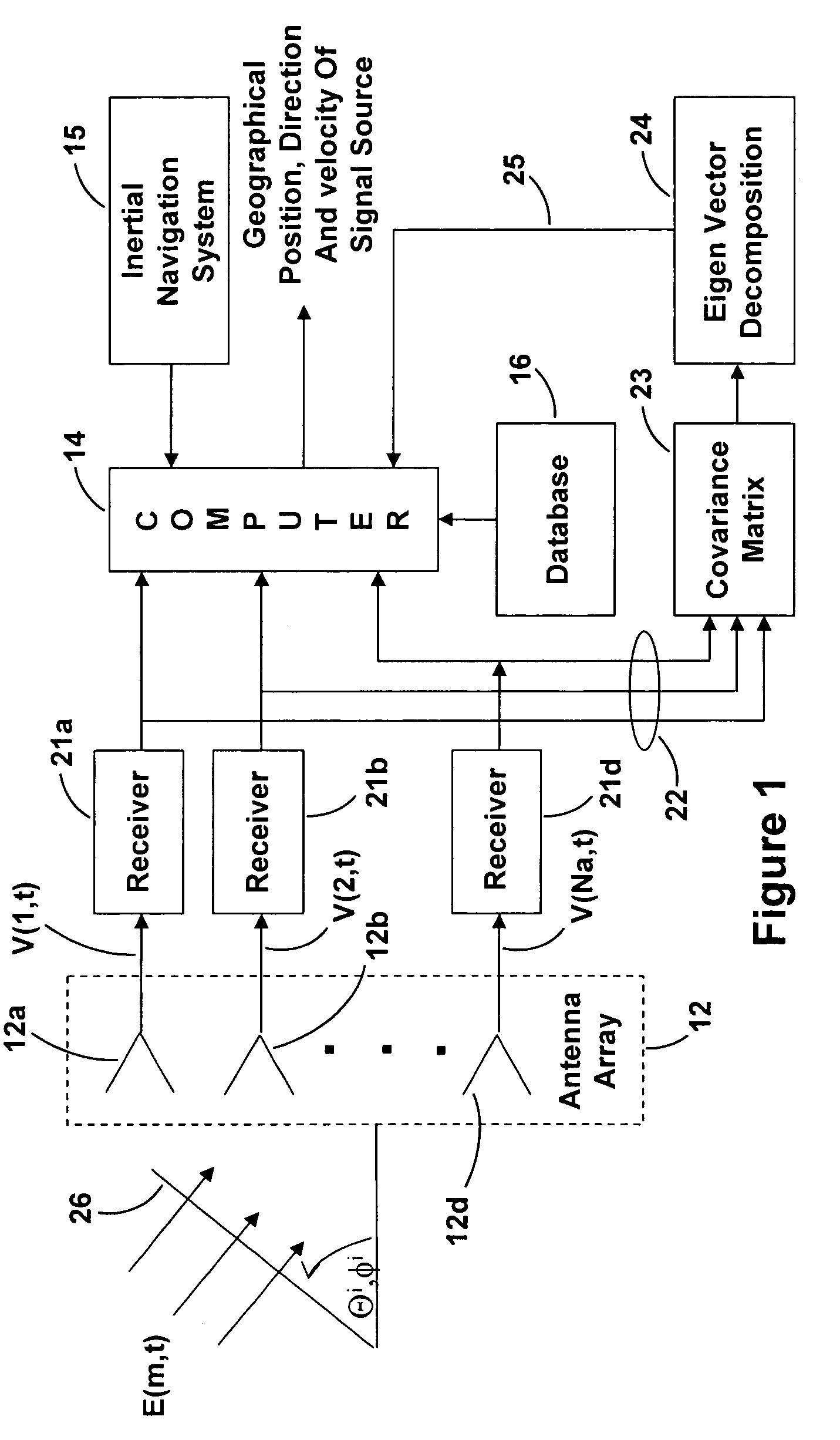
[0041]In the following detailed description and the drawings there are numerous terms used that are defined below:[0042]A(θ,φ)=the calibration array manifold and there is a different manifold for use with received signals at different frequencies.[0043]Vc(θi, φj) and Hc(θi, φj) vertical and horizontal array calibration measurements[0044]ρk=polarization vector.[0045]AOA=angle of arrival.[0046]CIDF=Correlation Interferometer Direction Finding.[0047]MT-CIGL=Moving Transmitter Correlation Interferometer Geo-Location.[0048]DF=direction finding.[0049]E=electromagnetic radio waves incident on the array of antennas.[0050]Me=the number of data sets made from the received signal, 180 herein[0051]Na=number of antennas in the beam forming / direction finding array, 4 herein.[0052](O)*=complex conjugate of (O).[0053](ip, qd)=in-phase and quadrature-phase of a complex quantity.[0054]PI-CIGL=polarization independent correlation interferometer geo-location.[0055]|R(xi,yj)|2=global correlation surface...


PUM


Abstract

A Moving Transmitter Correlation Interferometer Geo-Location (MT-CIGL) system is disclosed that permits locating both moving and stationary transmitters from moving DF equipment. A conjugate gradient based search routine is utilized which solves for the location of moving and stationary transmitters at the start of each measurement sequence and then solves for the velocity and direction of motion of the moving transmitter. This information is used to track the moving transmitter. Received signals are sampled, digitized and stored in covariance matrices. They are then summed and normalized using an equation that has velocity terms that are set to zero to minimize extraneous correlation peaks, and a maximum correlation peak is developed. A conjugate gradient search routine is used to find the correlation peak of the summed data. The value of the peak is then analyzed to see if it is above or below a predetermined value. If the peak value is above the predetermined value the transmitter is stationary and the located correlation peak is the location of the transmitter. If the peak value is below the predetermined value the transmitter is moving and the peak does not indicate the correct location of the transmitter. Another conjugate gradient search routine is performed using the previous erroneous peak as the starting point for the search to identify the actual location of the moving transmitter at the beginning of a search sequence. That location is then processed through the same equation, but without the velocity terms set to zero, to calculate the velocity and direction of motion of the transmitter. This information can then be used to plot a track for the moving transmitter.

Description

FIELD OF THE INVENTION[0001]The present invention relates to direction finding and, more particularly, to correlating signals received from a remote moving transmitter to determine the geographical location of the remote moving transmitter.BACKGROUND OF THE INVENTION[0002]In the earliest prior art the method of locating the position of a remote, stationary transmitter was to utilize a direction finding (DF) triangulation technique where signals from the transmitter are received at widely spaced DF antenna sites. A line-of-bearing (LOB) measurement to the transmitter is measured at each antenna site. When the LOBs are plotted on a map they intersect at the transmitter location. The accuracy of this intersection is directly related to the accuracy of these lines-of-bearing.[0003]A typical radio frequency interferometer system computes an angle of arrival (AOA) of a signal received from a remote, stationary transmitter by utilizing the phase difference of the transmitter signal arrivin...

Claims


Application Information

Patent Timeline
IPC IPC(8): G01S5/02G01S19/29
CPCG01S5/04G01S3/74G01S7/4021
Inventor STRUCKMAN, KEITH A.
Owner BAE SYST INFORMATION & ELECTRONICS SYST INTERGRATION INC
Why Eureka
Try Eureka