Dynamic wireless network

Active Publication Date: 2007-09-11
MODULAR MINING SYSTEMS
View PDF10 Cites 50 Cited by
  • Summary
  • Abstract
  • Description
  • Claims
  • Application Information

AI Technical Summary

Benefits of technology

[0036]It is another object of this invention to provide a Dynamic Wireless Network wherein a Distributed Routing Tree is dynamically configured to minimize transmissions hops, maximize signal strength, or optimize bandwidth.
[0037]It is yet another object of this invention to provide a Dynam

Problems solved by technology

Although simple communications bridges between two devices may be made using Layer 2 protocols, such simple bridges are inefficient for complex routing involving multiple communications subnets or multiple transmission hops.
Additionally, Layer 2 bridges cannot accommodate hardware devices or subnets utilizing different Layer 2 protocols.
One problem with 802.11 wireless networks is that they incur a high percentage of lost packets (packets which are transmitted by one device, but are not received by the target).
However, this re-transmission requirement does not apply to Broadcast messages.
802.11 wireless networks typically experience packet loss rates of 10-20%, making broadcast messaging extremel

Method used


Image

  • Dynamic wireless network
  • Dynamic wireless network
  • Dynamic wireless network

Examples


Example

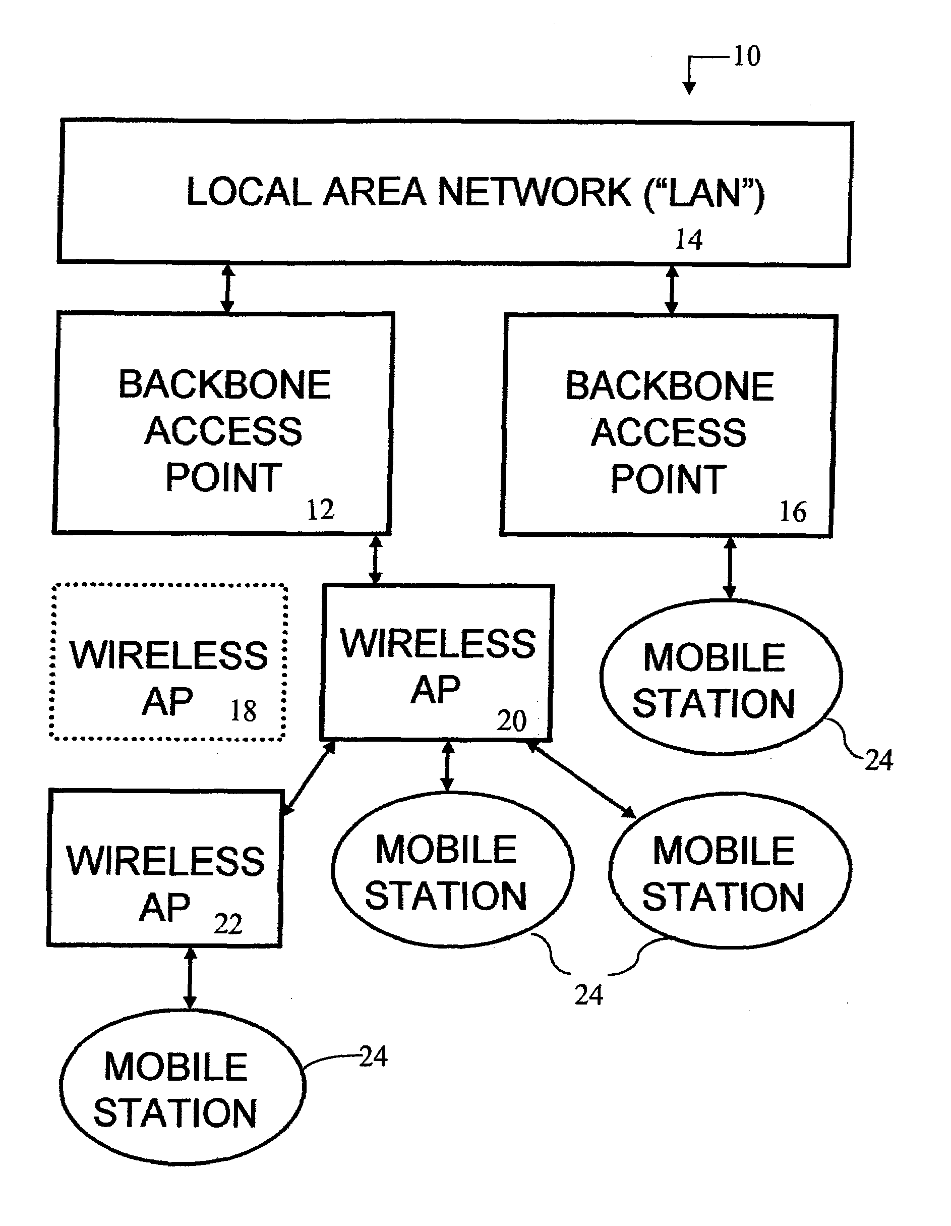
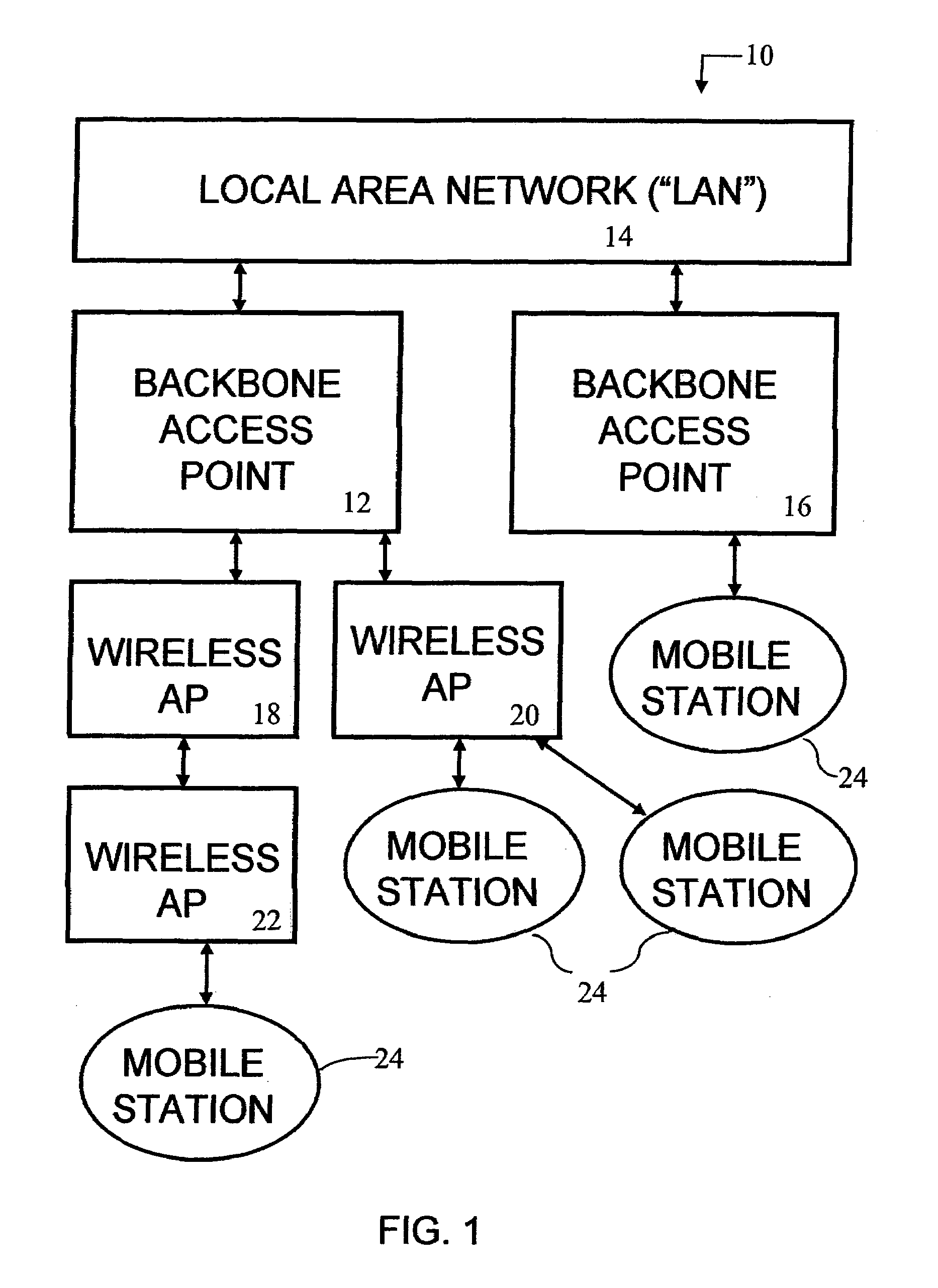
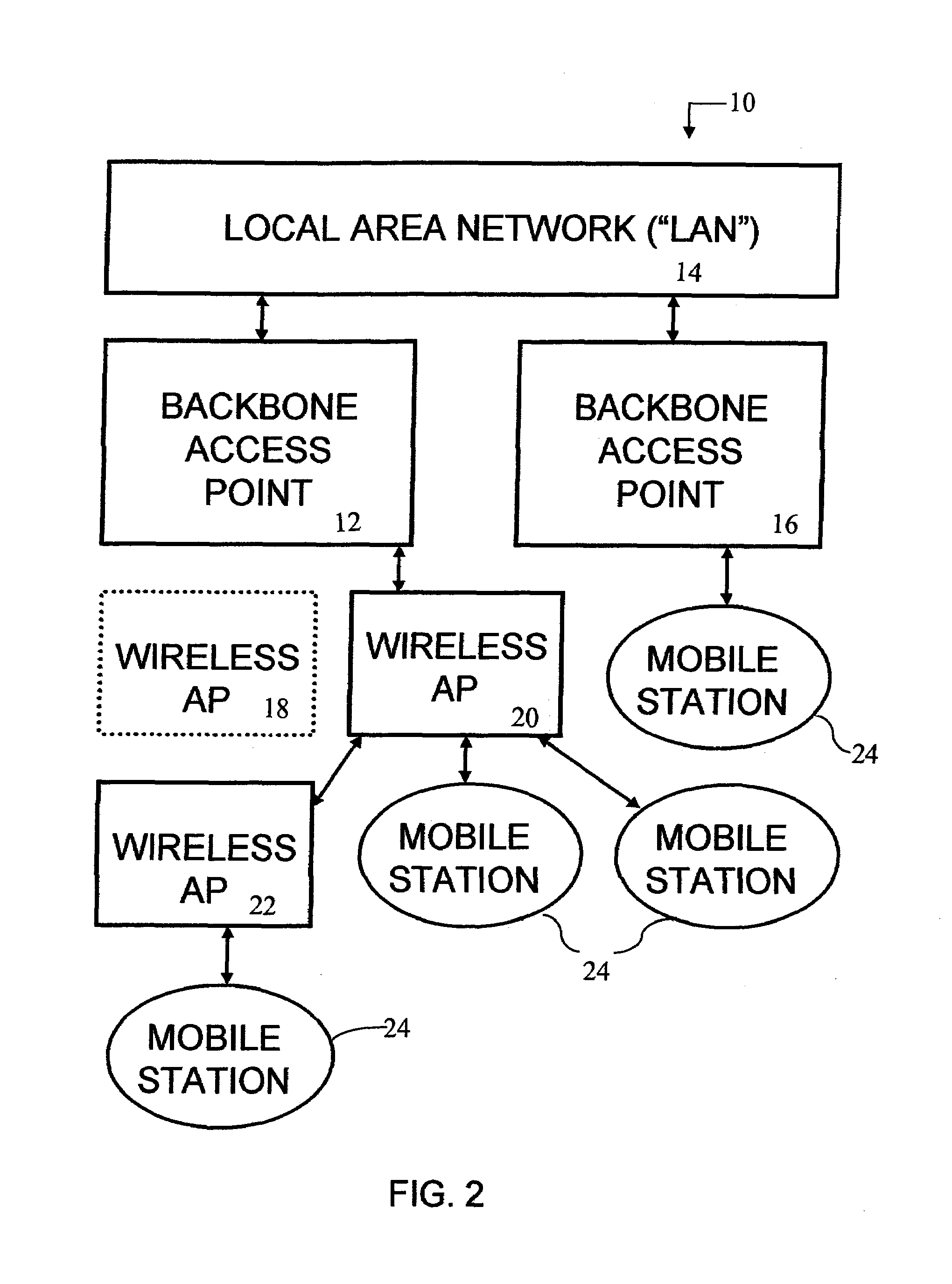
[0048]As a general overview of the invention, the block diagram of FIG. 1 shows a Dynamic Wireless Network 10. A first Backbone Access Point (“Backbone AP”) 12 is electrically connected to a Local Area Network (“LAN”) 14. Optionally, additional Backbone APs 16 may also be connected to the LAN 14. A First Level Wireless Access Point 18 is connected to the first Backbone AP 12 by the transmission and reception of radio frequency (“RF”) signals. Other First Level Wireless Access Points 20 may be connected to Backbone APs 12,16. One or more Second Level Wireless Access Points 22 may also be connected to the First Level Wireless Access Points 18,20 using RF signals. In this manner, subsequent levels of Wireless Access Points may be utilized to increase the range and coverage area of the Dynamic Wireless Network 10. The term Access Point (“AP”) is used to reference both Backbone APs 12,16 and Wireless APs 18,20,22.

[0049]Mobile Stations 24 are portable devices such as laptop personal compu...


PUM


Abstract

A Dynamically Reconfigurable Dynamic Wireless Network for connecting a local area network (“LAN”) to wireless Mobile Stations. Backbone Access Points (“Backbone APs”) are physically connected to the LAN. Levels of Wireless Access Points (“Wireless APs”) are daisy-chained together and connected to the Backbone AP, providing an extended area of network coverage. Mobile stations are connected to either Backbone APs or Wireless APs. Dynamic Reconfiguration prevents single point failures. Each AP contains a router, Address Resolution Protocol (“ARP”) cache, and Distributed Routing Table (“DR Table”). The DR Table maintains the Media Access Control (“MAC”) address and the Internet Protocol (“IP”) address of each AP below it in the Distributed Routing Tree. Additionally, each DR Table also maintains the IP address for the device each AP is connected. The Distributed Routing Tree is dynamically reconfigured to minimize transmission hops or to maximize signal strength between Mobile Stations and the LAN.

Description

FIELD OF THE INVENTION[0001]This invention is related in general to the field of wireless communications networks for use with wired local area networks (“LANs”). In particular, the invention consists of a wireless LAN comprised of direct link Access Points (“APs”), virtual link APs, mobile stations, and UHF / VHF broadcast networks.BACKGROUND OF THE INVENTION[0002]It is well known in the art that wireless transmitters and receivers called Access Points (“APs”) may be physically attached to Local Area Networks (“LANs”) such as Ethernet networks conforming to IEEE standard 802.3. Following the IEEE 802.11b standard, Mobile Stations may be connected to the APs through the transmission and reception of radio signals.[0003]As Mobile Stations transmit information to an AP, the AP may either broadcast the information to other wirelessly connected Mobile Stations or may pass the information to the attached Ethernet. Signals originating from the wired LAN can be transmitted to Mobile Station ...

Claims


Application Information

Patent Timeline
IPC IPC(8): H04L12/56H04L12/28
CPCH04W84/12H04W40/02H04W80/02H04W88/08
Inventor OLSON, JONATHAN P.BENTLEY, KEVIN R.
Owner MODULAR MINING SYSTEMS
Why Eureka
Try Eureka