
Steerable diagnostic catheters

a catheter and catheter technology, applied in the field of medical diagnostic equipment, can solve the problems of inability to easily see defects, inability to remove catheters, and inability to damage the organ itself, so as to achieve the effect of small size, small basket size and shape, and easy modification

Inactive Publication Date: 2007-09-11
MOGUL JAMIL
View PDF6 Cites 87 Cited by
  • Summary
  • Abstract
  • Description
  • Claims
  • Application Information

AI Technical Summary

Benefits of technology

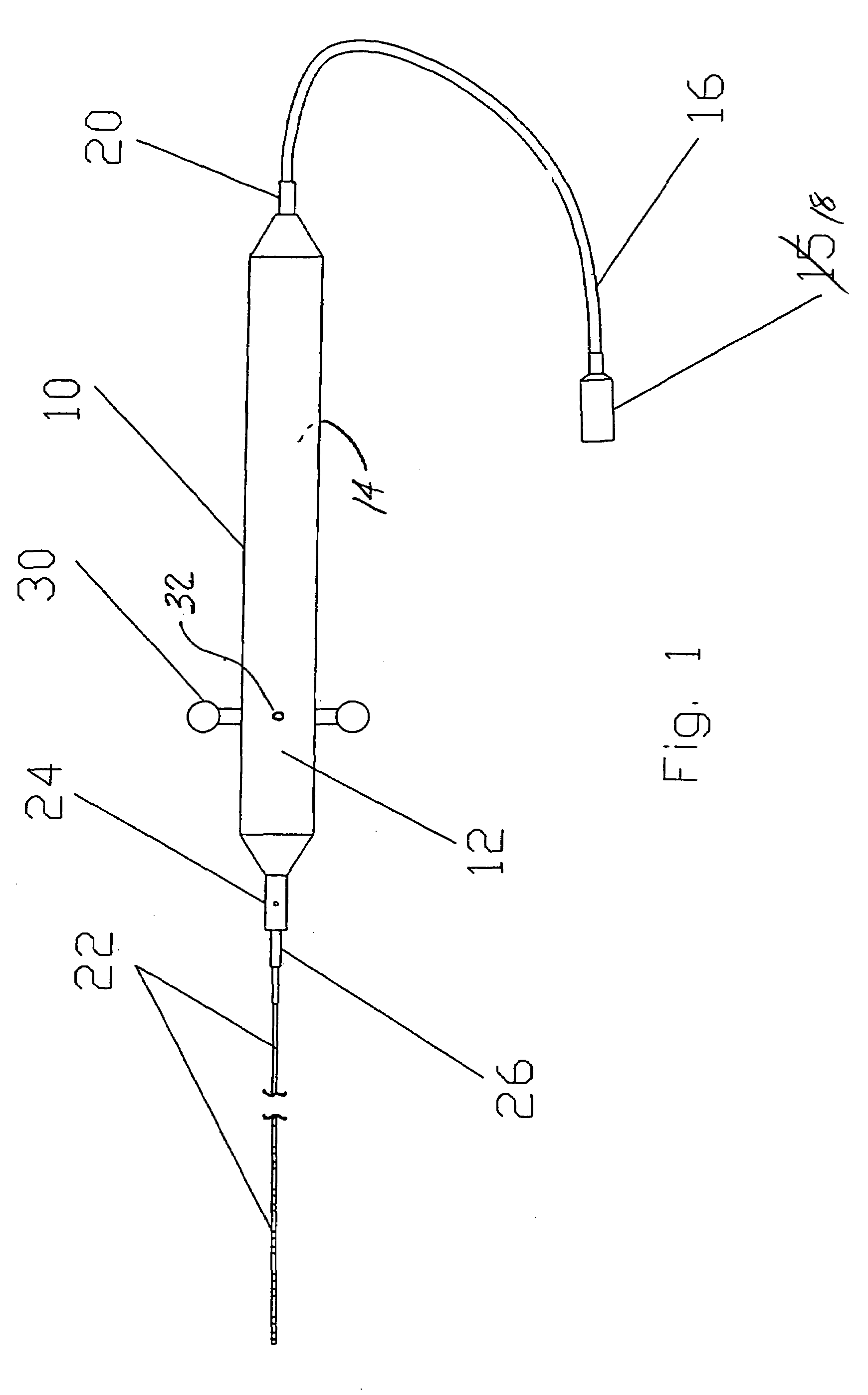
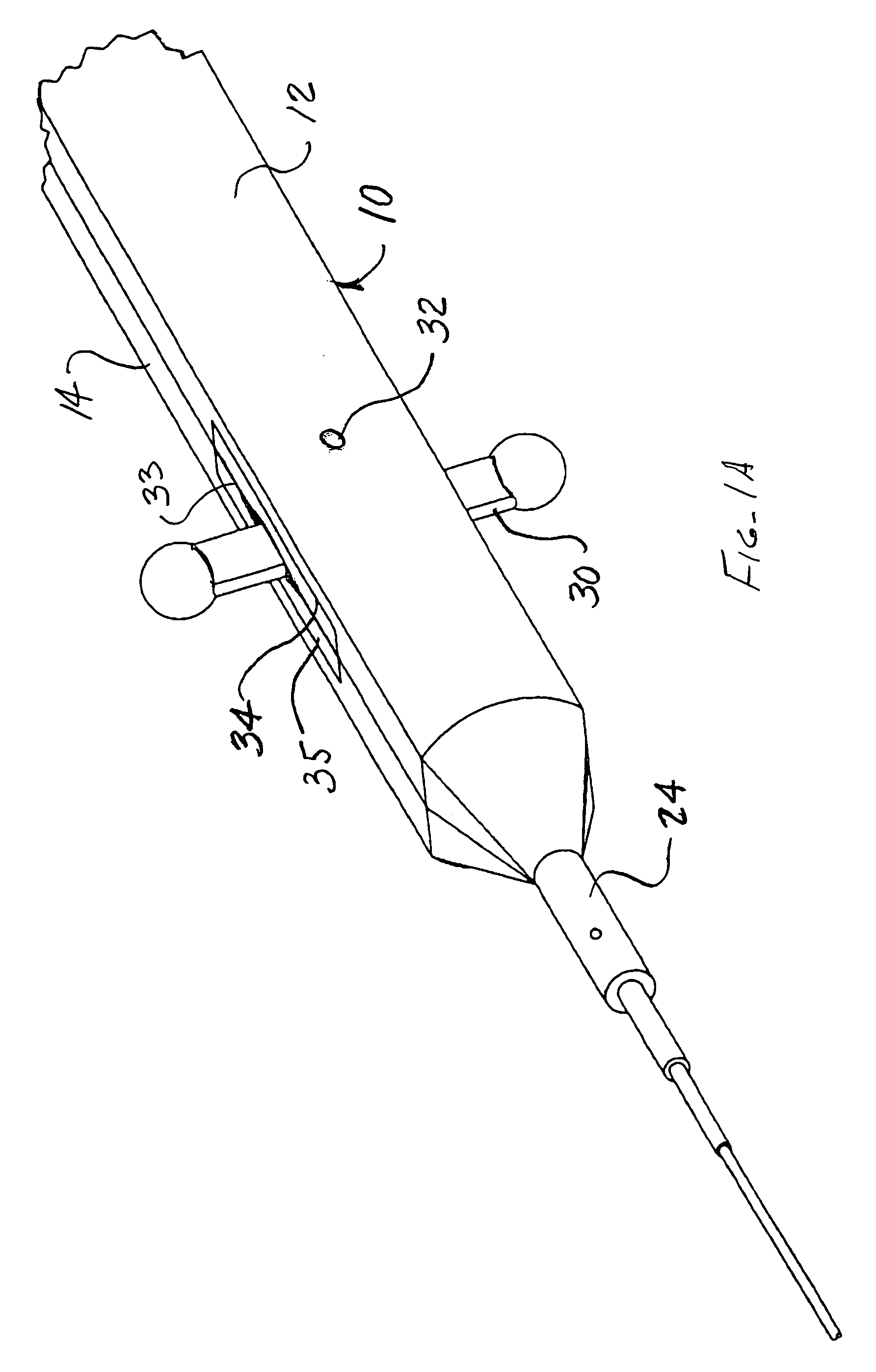
[0014]An advantage of the present invention is that although it is smaller in size than most current art devices, it can be steered in the vessel or organ being examined.
[0015]Another advantage of the present invention is that it has a large plurality of non-welded ring electrodes for sensing, even though the catheter is smaller in size than most current art devices.
[0016]A still further advantage of the present invention is that the distal end of the fixed shape of the catheter can be formed and fixed in any shape desired by the user.
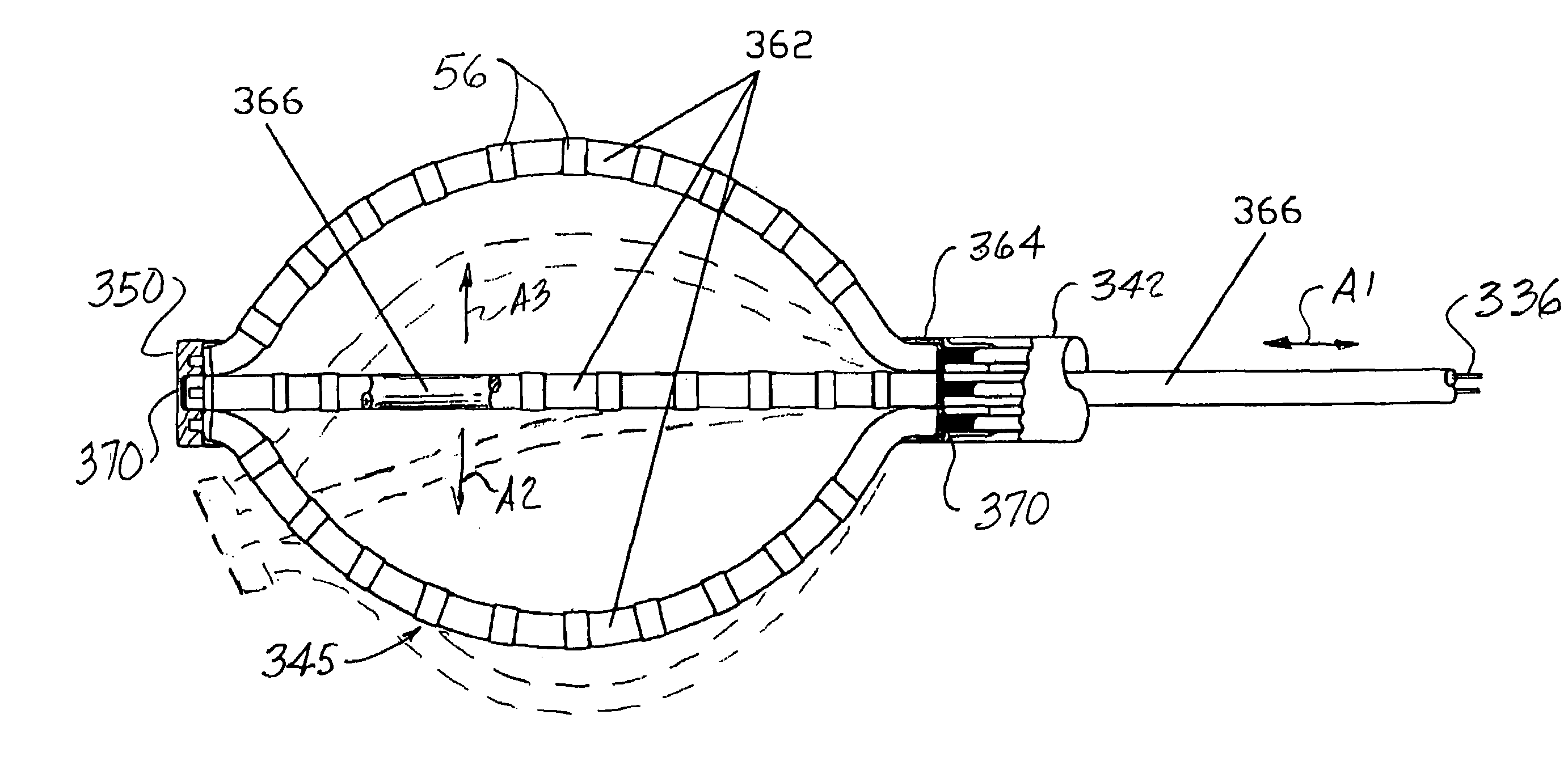
[0017]Another advantage of the present invention is that when it is used as a basket catheter, the basket size and shape can be modified while the catheter is in use.
[0018]Yet another advantage of the present invention is that when the basket catheter version is in use, the basket can be steered in either expanded or collapsed state within the vessel or organ being examined.
[0019]Still another advantage of the present invention when it is used as a basket catheter is that no sheath is necessary for insertion of the catheter into the vessel or organ.

Problems solved by technology

One of the chief difficulties in examining the heart is that, as with all internal organs, the defects cannot be readily seen.
When this is the case, the catheter entry path becomes very congested.
Due to the relatively large size of existing diagnostic catheters, it is sometimes necessary to remove one catheter and replace it with another during a procedure.
In addition to the distinct possibility of dislodging the already positioned catheters, the removal of a catheter can itself damage the organ if the catheter is removed improperly or becomes entangled with another catheter.
Another of the shortcomings in the prior art catheter devices is that they are very difficult to position correctly in the vessel or organ being examined.
There are only very limited means of guiding the catheter.
Another problem inherent in the prior art devices is that the shape of the probes on the distal ends of the catheters is fixed.
This contributes to the problem of congestion in the entry path, as a different catheter must be introduced when the physician wishes to examine different vessel and organ wall shapes and sizes.

Method used


Image

  • Steerable diagnostic catheters
  • Steerable diagnostic catheters
  • Steerable diagnostic catheters

Examples


first embodiment

[0079]FIGS. 9-9C illustrate in some detail the structure of an alternate embodiment of the present invention having a catheter body 22′ that likewise forms a bi-directionally steerable catheter means. As with the first embodiment, a proximal portion of the catheter body 22′ is formed by a braided tubing 42′. A distal or probe end assembly 45′ of the catheter body 22′ is formed by a tubular member 44′ having a pair of longitudinally extending lumens 54′ formed therein through which the steering wire 36 is passed. A first joint 46′ is formed at the point where the braided proximal portion 42′ meets the probe end member 44′. A second joint 48′ is formed where a distal tip 50′ is attached to the member 44′.

[0080]As opposed to the first embodiment of the bi-directionally steerable unit, in this embodiment, a separate steering wire guide (52 in FIGS. 7 and 7A) is not utilized. As is perhaps best illustrated in FIGS. 9 and 9A, the distal tip 50′ contains no anchoring means for the steering...

second embodiment

[0091]As shown in FIG. 17, the unidirectionally steerable catheter probe end assembly 145′ also utilizes a solderless (weldless) connection method to make ohmic contact between each signal wire 28 and a corresponding ring electrode 56.

[0092]FIGS. 19-21 illustrate the structure of a fixed curve shaped catheter probe end assembly 245. The structure of the catheter body is equivalent to that of the steerable embodiments, with a proximal portion of the catheter body covered with a braided tubing 242, and a distal or probe end member 244 of the catheter body formed by an eleven lumen tube. A first joint 246 is formed at the point where the distal end of tubing 242 meets the proximal end of the probe member 244. The fixed curve shaping of the probe member portion of the catheter body is accomplished by forming a deformable member 255, such as a spring or flexible rod, or even a rubber or plastic material in a state or condition such that when cooled or cured it will form a curved member t...


PUM


Abstract

A diagnostic catheter with a steering device to direct the distal end of the catheter while it is inserted in a vessel. The catheter may include either a bi-directional steering mechanism, or a unidirectional steering mechanism. Pre-formed catheters with no steering means are also provided. The catheter bodies include a plurality of ring electrodes used for sensing the intracardial electrogram signal during operation of the catheter. The ring electrodes are placed in ohmic contact with their corresponding signal wires by a solderless connection. In addition, the catheter may be embodied as a basket catheter including a plurality of splines. After the catheter is inserted into the vessel or organ to be examined (typically the heart), the splines may be expanded from an at-rest position to form the basket. A central retractable and steerable member is included to provide the expansion force. The expansion force can also be provided by moving the proximal portion of the catheter relative to the central member. Each of the splines forming the basket includes a length of spring wire disposed therein to provide conformal forces causing the splines to conform to the surfaces being inspected.

Description

CROSS REFERENCE TO RELATED APPLICATIONS[0001]This application is a divisional of U.S. patent application Ser. No. 10 / 099,576 which was filed on Mar. 14, 2002 now U.S. Pat. No. 6,829,497, which is a continuation-in-part of U.S. patent application Ser. No. 09 / 399,929, filed Sep. 21, 1999, now abandoned, the specifications and drawings of which are incorporated herein by reference.FIELD OF THE INVENTION[0002]The present invention relates generally to medical diagnostic equipment, and more particularly is a new construction for steerable diagnostic catheters.BACKGROUND OF THE INVENTION[0003]Heart disease is one of the leading causes of death in the world. Heart disease is found in all countries and across all ages, socioeconomic levels, occupations, and sexes. Because heart disease is so universally common, the diagnosis and treatment of heart disease is an immensely important field.[0004]One of the chief difficulties in examining the heart is that, as with all internal organs, the defe...

Claims


Application Information

Patent Timeline
IPC IPC(8): A61B5/042A61M25/01
CPCA61B5/0422A61B5/6858A61M25/0136A61M25/0144A61M25/0147A61B2562/0209A61B2562/043A61M2025/015A61B5/287
Inventor MOGUL, JAMIL
Owner MOGUL JAMIL
Learn More