

Cutting tool for rotating and drilling into solid blocks
- Summary
- Abstract
- Description
- Claims
- Application Information
AI Technical Summary
Benefits of technology
Problems solved by technology
Method used
Image

Examples
Embodiment Construction
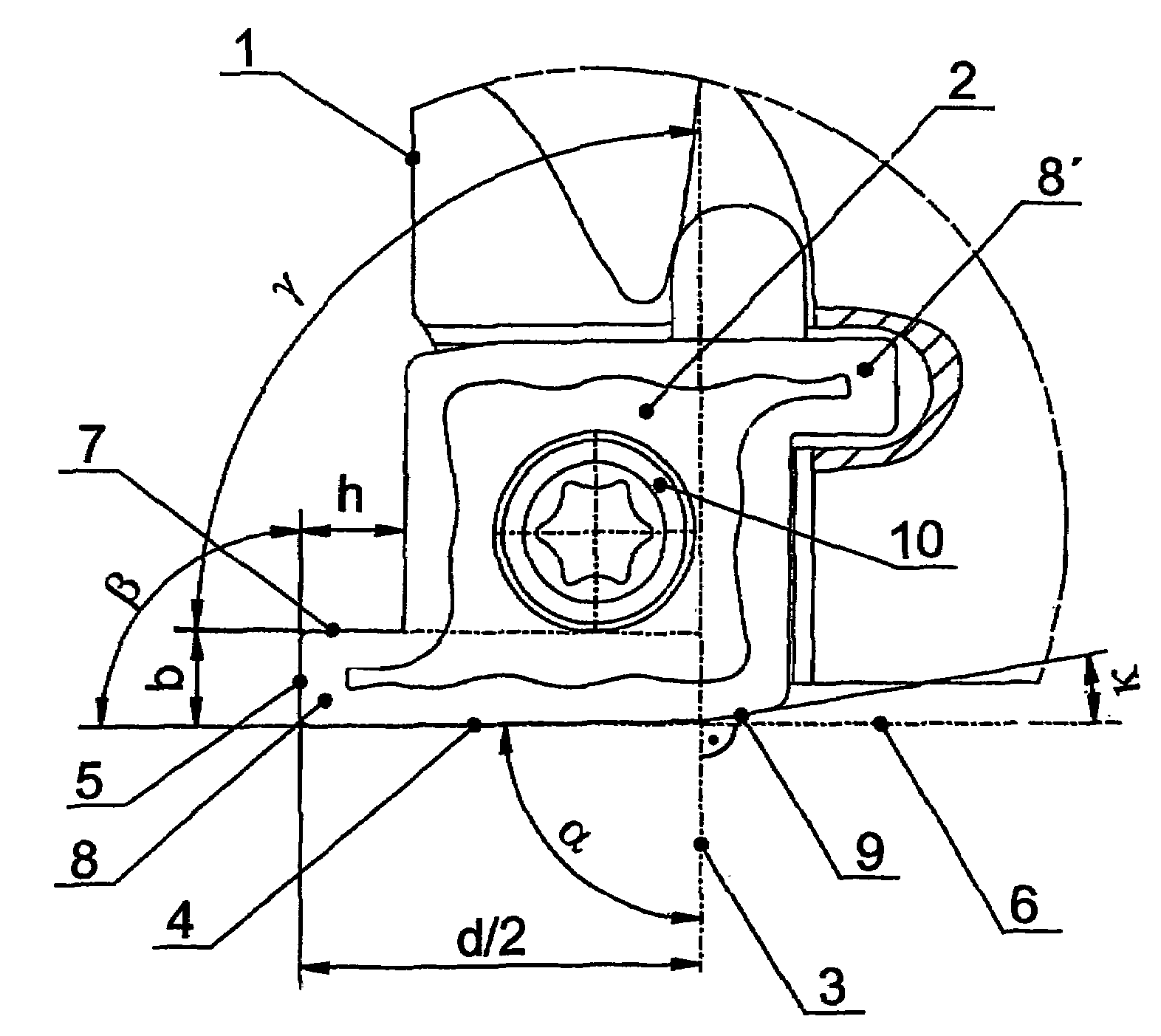
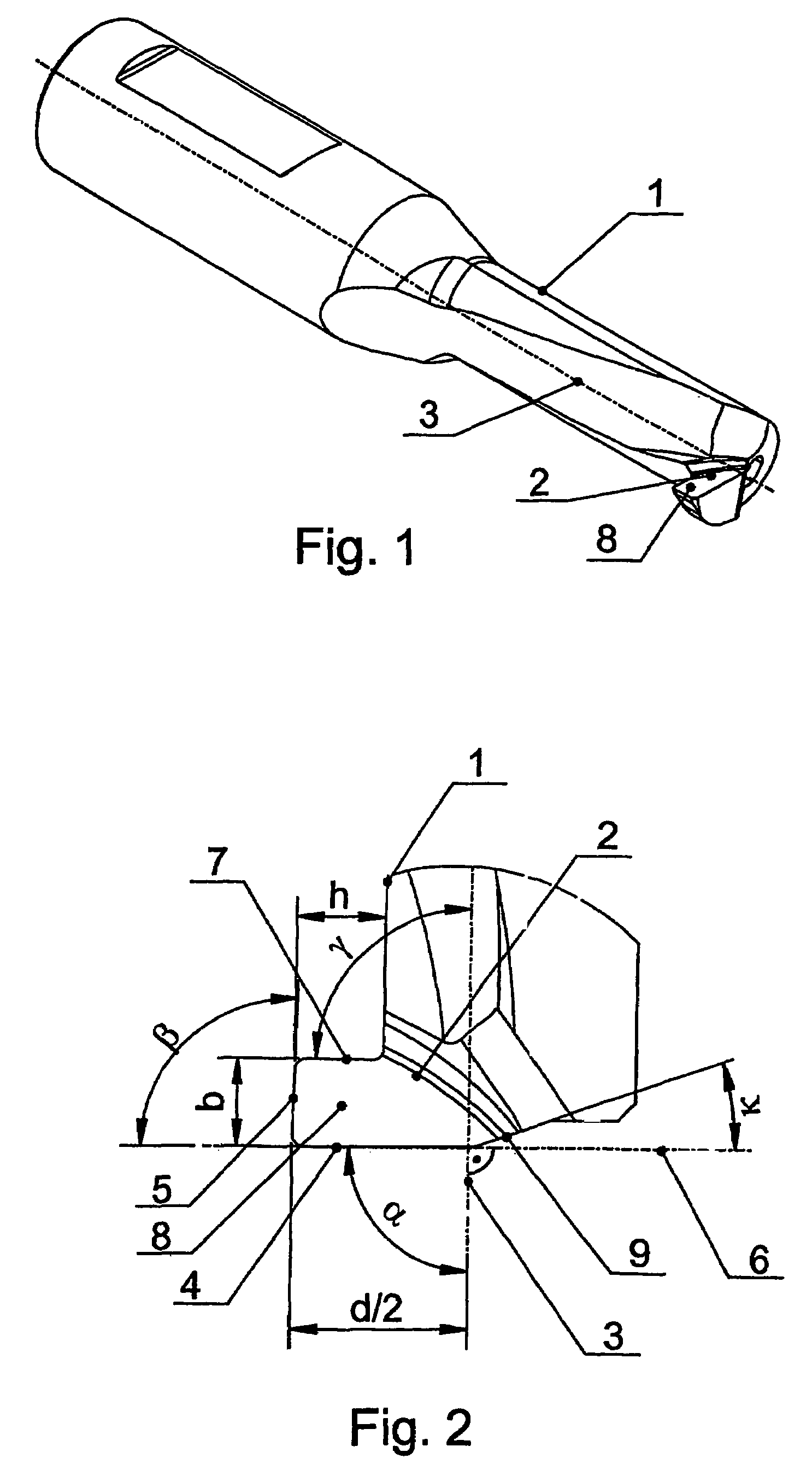
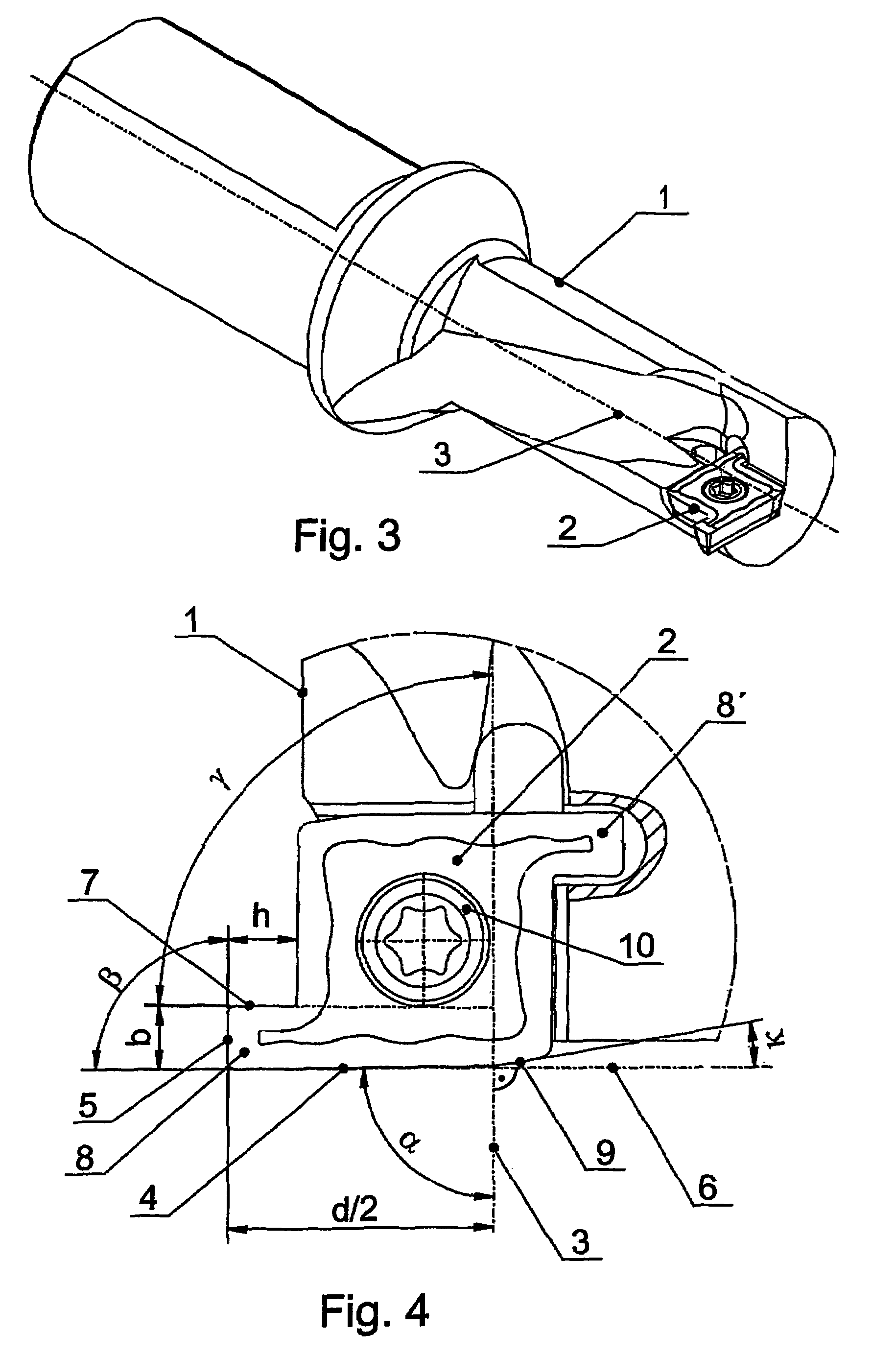
[0022]FIG. 1 illustrates a cutting tool according to the invention for boring into solid material. In this specific embodiment, the cutting head 2 is produced in one piece with the shank 1 from hard metal. The specific embodiment of the cutting head 2 can be seen in detail from FIG. 2. The cutting head 2 has a section 8 which projects laterally from the drill shank 1 with a height h which is 25% of the drill diameter and a width b which is 25% of the drill diameter. The ratio of height h to width b is 1:1.
[0023]The end of the cutting head 2 is formed as a front cutting edge 4, which runs continuously straight as far as the drill axis 3 of the cutting tool and forms an angle α of 89.5° with the drill axis 3. Beyond the drill axis 3, the front cutting edge 4 merges into an angled cutting section 9, which forms an angle κ of 20° with a perpendicular 6 to the drill axis 3. The projecting section 8 of the cutting head 2 has at the side a straight cutting edge 5, which cuts the wall of th...
PUM
| Property | Measurement | Unit |
|---|---|---|
| Fraction | aaaaa | aaaaa |
| Fraction | aaaaa | aaaaa |
| Angle | aaaaa | aaaaa |
Abstract
Description
Claims
Application Information