Cutting insert and gear cutter

Pending Publication Date: 2022-05-12
TUNGALOY CORP
View PDF0 Cites 0 Cited by
  • Summary
  • Abstract
  • Description
  • Claims
  • Application Information

AI Technical Summary

Benefits of technology

The present invention provides a cutting insert for a gear cutter that has excellent manufacturing performance and dimensional accuracy. The cutting insert is formed with a wedge-shaped mounting seat that is compatible with the tool body, allowing for the formation of a pair without interfering with the adjacent protruding strip parts. This ensures the excellent performance of the tool body and reduces the burden of inventory management of consumables. The cutting insert also allows for the machination of both tooth faces of a gear with a single cutting blade and provides economy. Overall, the present invention provides a cutting insert that is superior in both manufacturing performance and dimensional accuracy.

Problems solved by technology

In such a positional relationship, as referred to in FIG. 6 in the present application, when a screw hole is formed in the protruding strip part so as to manufacture the tool body, a tap for tapping, a drill for a prepared hole or the like interferes with the projecting strip part on the adjacent mountain in parallel with the projecting strip part in which the screw hole is to be formed, and it is difficult to manufacture the tool body which forms a pair with the throwaway chip.
Since the throwaway chip cannot be disposed at a portion of the cutting pocket, it increases limitation in design.
On the other hand, with Patent Publication JP-A-2013-233648, since it is an assembling type, machining errors of the plurality of protruding strip parts are accumulated on the tool body.

Method used


Image

  • Cutting insert and gear cutter
  • Cutting insert and gear cutter
  • Cutting insert and gear cutter

Examples


Embodiment Construction

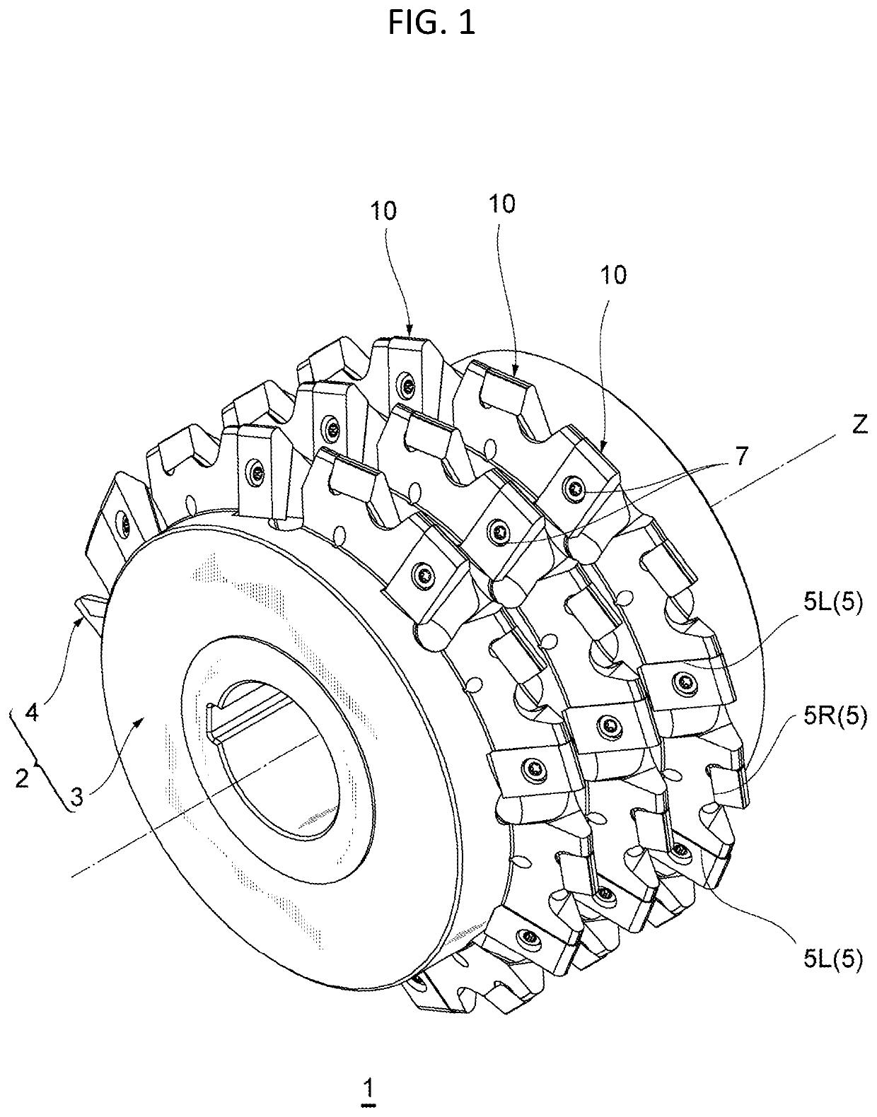
[0023]By referring to the attached drawings, a preferred embodiment of the present invention will be described. In each of the drawings, those given the same reference numerals have the same or similar structures. A gear cutter 1 according to an embodiment of the present invention is a cutting-edge replacement type hob and a gear cutter similar to that, and by mounting it on a hobbing machine and rotating it, a tooth profile of a gear or the like can be cut on an outer peripheral face of a work rotated synchronously by a generating method.

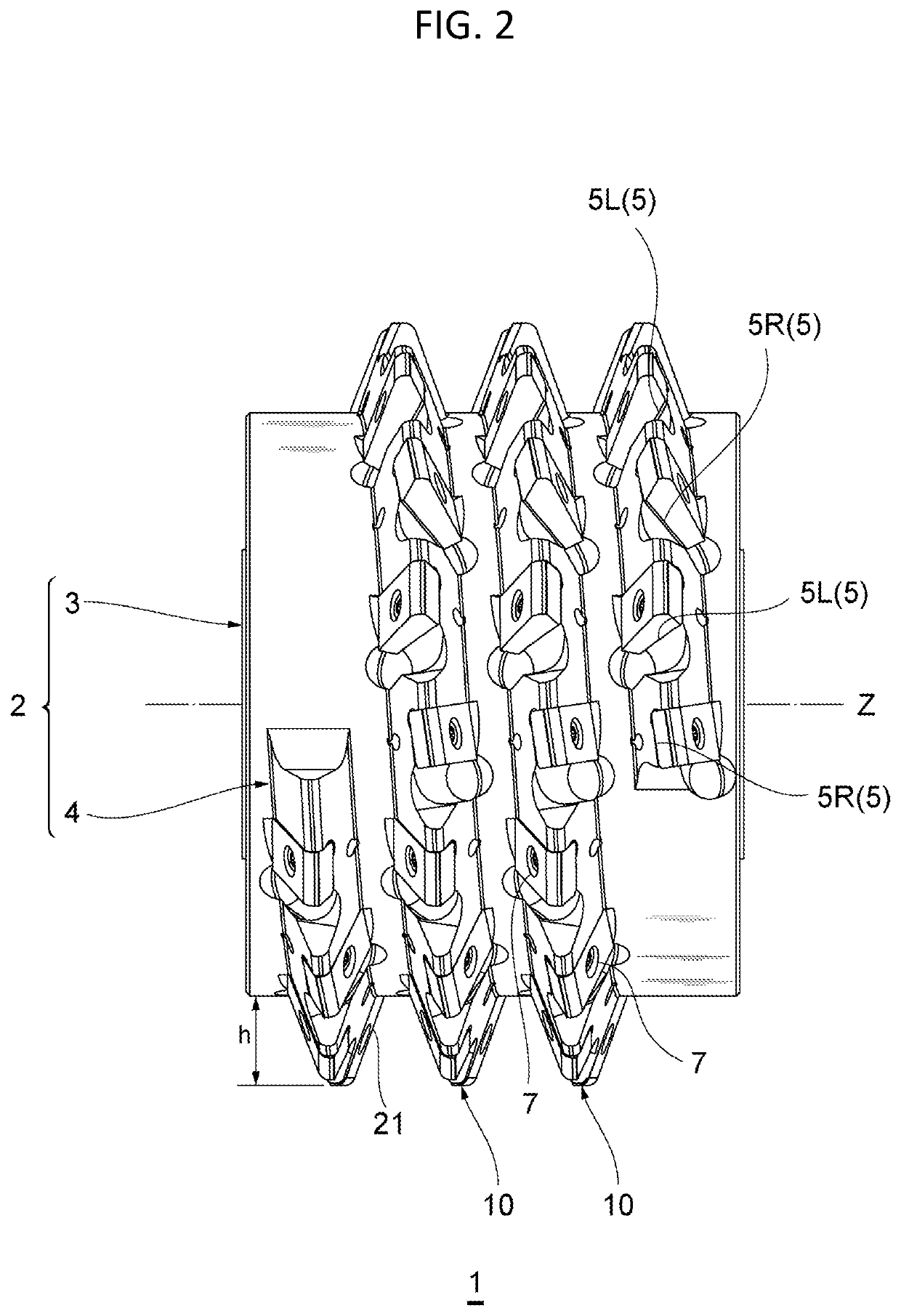
[0024]FIG. 1 is a perspective view illustrating an example of the gear cutter 1 according to an embodiment of the present invention. As illustrated in FIG. 1, the gear cutter 1 includes a plurality of replaceable cutting inserts 10 and a tool body 2 fixing the cutting inserts 10. The tool body 2 has a cylindrical part 3 formed having a substantially cylindrical shape, a protruding strip part 4 provided spirally on an outer peripheral face of the cy...


PUM


Abstract

A cutting insert which is excellent both in manufacturing performances and dimensional precision and forms a pair with a tool body and a gear cutter including the cutting insert are provided. A cutting insert has a first face which is a rake face, a second face, a peripheral side face, and a mounting hole. On a ridge line where the first face and the peripheral side face cross each other, a cutting blade is formed. The cutting blade includes a corner part capable of machining a tooth bottom of a gear, and a main part extending to the corner part. The peripheral side face includes an inner side face in contact with a tool body and a first flank facing the main part. The mounting hole penetrates the first flank and the inner side face so that a center axis crosses the inner side face perpendicularly. The cutting insert is formed having a wedge shape such that thickness of the first flank and the inner side face becomes smaller as it goes from one end to the other end.

Description

CROSS-REFERENCES TO RELATED APPLICATIONS[0001]This application relates to and claims priority from Japanese Patent Application No. 2020-188022, filed on Nov. 11, 2020, the entire disclosure of which is incorporated herein by reference.BACKGROUNDField[0002]The present invention relates to a cutting insert and a gear cutter including the cutting insert.Description of Related Art[0003]There is known a gear cutter (Gear cutter) called a hob (Gear Hob). The hob has a substantially cylindrical shape, and a spiral protruding strip part having a cutting blade is formed on an outer peripheral face thereof. For example, Patent Publication JP-A-H09-117824 discloses a throwaway-chip direct-mounting type hob in which a replaceable throwaway chip is fixed to a tool body. In the flat-plate shaped throwaway chip disclosed in Patent Publication JP-A-H09-117824, as referred to in FIG. 3 in Patent Publication JP-A-H09-117824, the protruding strip part of an adjacent mountain (a “worm” in Patent Public...

Claims


Application Information

Patent Timeline
IPC IPC(8): B23F21/12
CPCB23F21/128B23F21/16B23F21/166B23C5/202B23C2200/367B23C2200/203
Inventor OGAWA, ATSUSHISUZUKI, AKIMICHI
Owner TUNGALOY CORP
Why Eureka
Try Eureka