
Method and apparatus for automated coverslipping

a technology of automatic covering and specimen, applied in the direction of instruments, analysis using chemical indicators, transportation and packaging, etc., can solve the problems of numerous coverglasses breaking, difficult to handle and separately remove coverglasses, and considerable bending moment applied in the middle of the coverglass, so as to reduce the possibility of static electricity and small restoring force

Active Publication Date: 2007-09-18
VENTANA MEDICAL SYST INC
View PDF16 Cites 38 Cited by
  • Summary
  • Abstract
  • Description
  • Claims
  • Application Information

AI Technical Summary

Benefits of technology

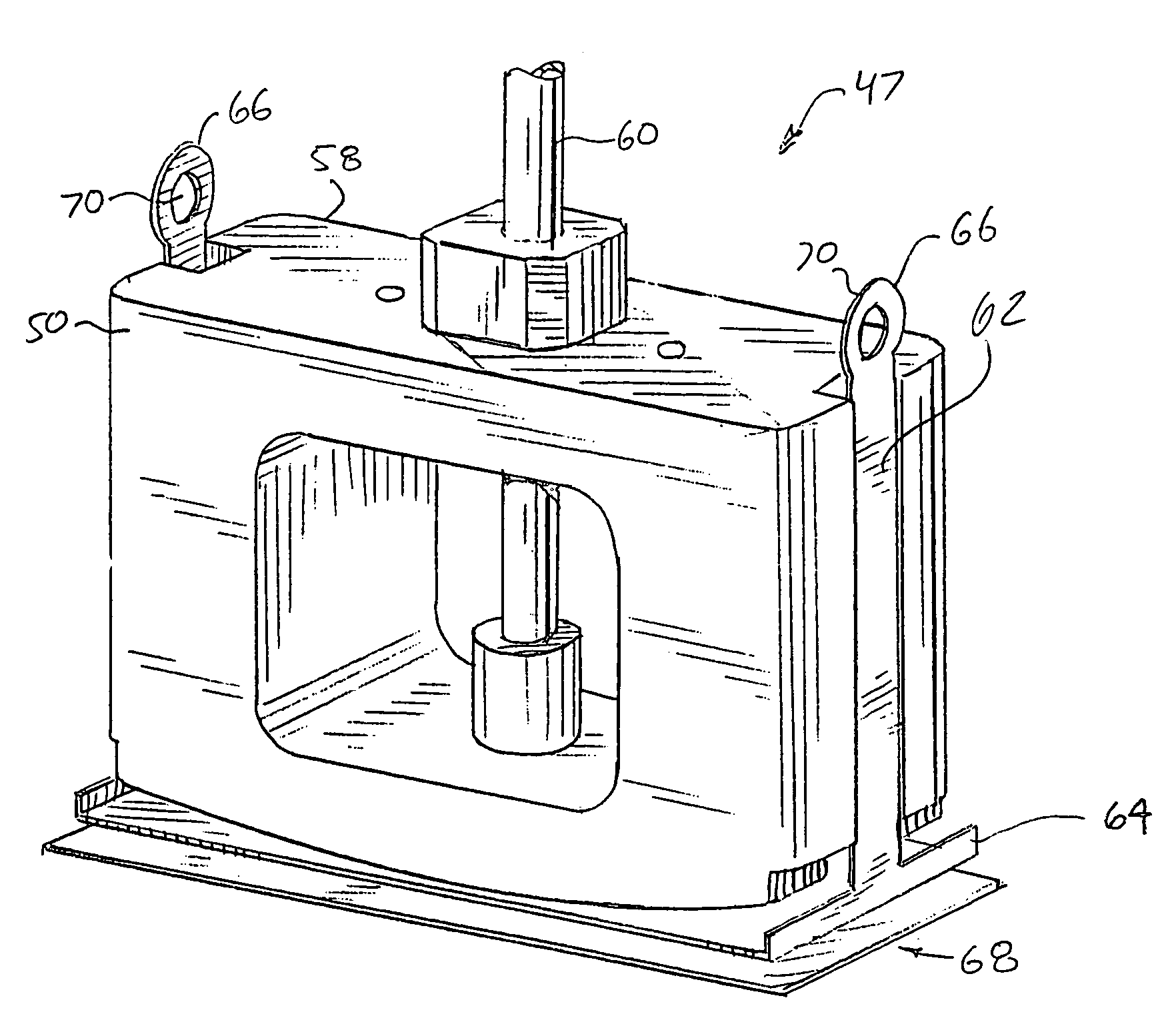
[0007]In one embodiment, the invention is directed to a method and apparatus for removing at least one coverglass from a stack of coverglasses. In one aspect, the method and apparatus removes the coverglass using a single sealing member. The sealing member forms a seal along a circumference of the coverglass (e.g., providing a seal along or proximate to the edges of the coverglass). The coverglass may then be bent using the single sealing member. The bending may include deforming the coverglass so that the coverglass has a constant or near constant bend radius (i.e., the curvature of the coverglass is approximately constant along the edge, preferably the longitudinal edge, of the coverglass). In one embodiment, the bending of the coverglass is performed using the sealing member in combination with a suction block. The suction block may be used as a support for the coverglass during deformation and may be shaped with a constant curvature so that when the coverglass is deformed, its shape has a constant (or substantially constant) bend radius. Greater separating force is generated along the edges while not overstressing other areas, which is less likely to break the coverglass and more likely to result in a separation of the coverglass. In this manner, the apparatus and method enable the separation of a coverglass from the stack of coverglasses. After selection of a coverglass, the stack of remaining coverglasses may be lowered and a curved barrier that may be matched to the shape of the bent coverglass wipes beneath the selecting device to remove any clinging coverglasses that may be present. Any coverglasses wiped from beneath the selected one will be placed back onto the remaining stack.
[0009]In the embodiment wherein the coverglass is held via a suctioning mechanism, the suctioning mechanism is turned off allowing the coverglass to fall onto the slide via gravity. Spring member(s) may be located in the flexible backing plate. The spring member(s), compressed by the force of the coverglass against the flexible backing plate, exert a small restoring force on the coverglass when it is released insuring the disengagement of the coverglass from the sealing member. Moreover, the coverglass may be held by a conductive sealing member. In this manner, the sealing member may be connected to ground, thereby reducing the possibility of static electricity causing the coverglass to cling after the suctioning mechanism is turned off.

Problems solved by technology

This stacking presents a problem: the coverglasses are difficult to handle and separately remove from the stack since they are fragile and may stick together easily.
Typically, to remove one coverglass from the stack, a considerable amount of bending moment is applied at the middle of the coverglass.
However, this action results in numerous coverglasses breaking because they are very fragile and the force applied was greater than the stability of the glass.
Furthermore, the bending action did not guarantee that only one coverglass was selected.
This presents other problems.
Electrostatic forces can hold the coverglass to the suction cups even after turning the mechanism off, making it difficult to apply the coverglass to the slide.
Moreover, the compression of the coverglass to remove air bubbles may cause the adhesive on the tissue sample to expel outward, thereby potentially contaminating other slides or other portions of the machine.

Method used


Image

  • Method and apparatus for automated coverslipping
  • Method and apparatus for automated coverslipping
  • Method and apparatus for automated coverslipping

Examples


Embodiment Construction

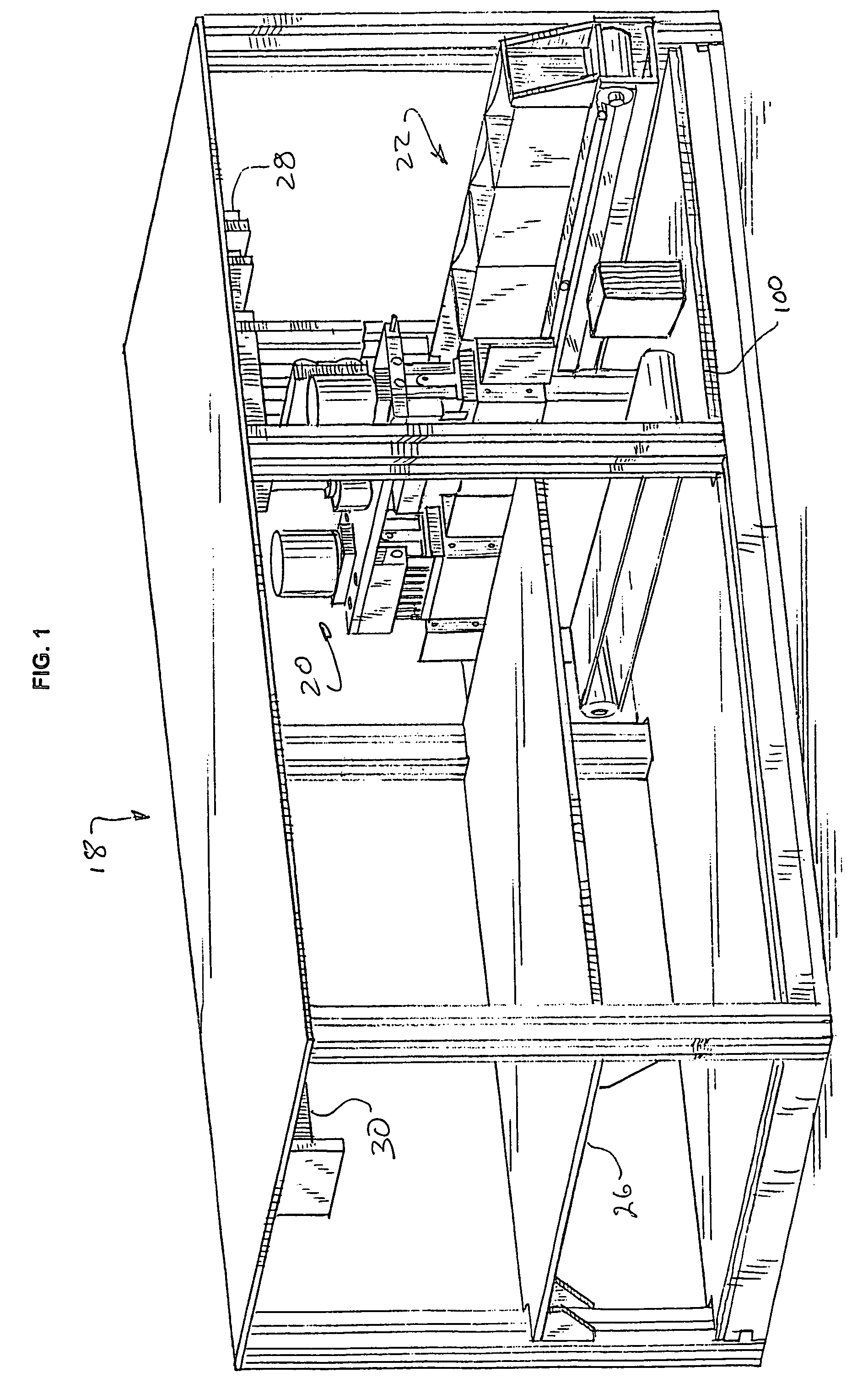
[0027]Referring to FIG. 1, there is shown a perspective view of an automated coverslipper module 18. The automated coverslipper module 18 includes a head portion 20 (see e.g., FIG. 3), a cartridge supply and dispense device 22 (see e.g., FIG. 7), and a flat portion 24 upon which a tray 26 (see e.g., FIG. 9) sits. The head portion 20 moves in one direction using motor 28 to move along rail 30.

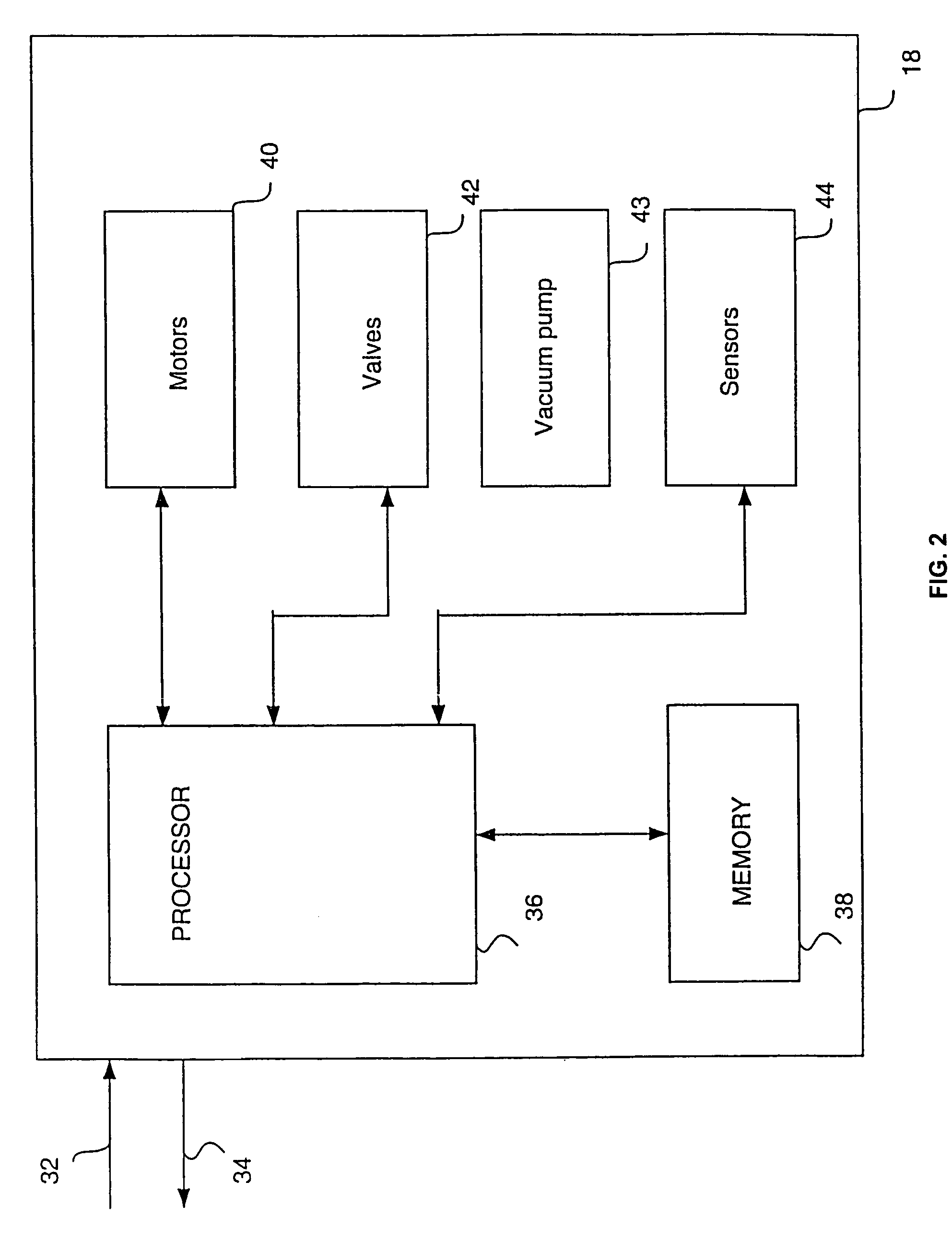
[0028]Referring to FIG. 2, there is shown a block diagram of the automated coverslipper module 18. The automated coverslipper module includes inputs / outputs 32, 34. In one embodiment, the automated coverslipper module is integral with other components of a tissue staining instrument (i.e., contained within a single device). See U.S. patent application Ser. No. 60 / 372,506 filed on Apr. 15, 2002 and incorporated by reference in its entirety. In an alternative embodiment, the automated coverslipper module may be a physically separate, yet electronically connected device, interacting with other modu...


PUM

PropertyMeasurementUnit
flexibleaaaaaaaaaa
constant curve radiusaaaaaaaaaa
conductiveaaaaaaaaaa

Abstract

An apparatus and method for selecting and dispensing coverglasses over specimens on slides for the purpose of viewing specimens through a microscope. The selecting device contains a suctioning mechanism for picking up a coverglass from a stack of coverglasses. It also contains the ability to bend the coverglass to assist in separating the coverglasses. The apparatus further contains a matched barrier to eliminate any coverglasses that may stick to the selected coverglass. The selecting device also contains spring members which aid in the dispensing of the coverglass. After the suctioning mechanism releases the coverglass, the spring members exert a force onto the coverglass to insure that it is released from the selecting device and placed onto the slide. After placement of the coverglass onto the slide, capillary action pushes air bubbles out from underneath the coverglass.

Description

[0001]This application claims the benefit of the filing date of application Ser. No. 60 / 375,925, filed on Apr. 26, 2002, the contents of which are incorporated herein in their entirety by reference.FIELD OF THE INVENTION[0002]This invention relates to a method and apparatus for automatically covering a specimen to be examined on a microscope slide with a tissue coverglass.BACKGROUND OF THE INVENTION[0003]Scientists examine numerous specimens placed on slides using microscopes. Typically, a specimen is covered with a thin transparent coverglass. This is done for several reasons. The coverglass can flatten the specimen so that the specimen is in the same viewing plane, thereby allowing one to view the specimen better. The coverglass provides protection for the specimen from the objective lens of the microscope should the lens be placed too closely to the slide. The coverglass may further provide a housing structure or an area by which the specimen will be permanently retained on the s...

Claims


Application Information

Patent Timeline
Patent Type & Authority Patents(United States)
IPC IPC(8): G01N35/00B65H1/08B65H3/08B65H3/46G01N1/28G02B21/34
CPCB65H1/08B65H3/46G01N1/2813G02B21/34B65H3/0816Y10T156/1132B65H2301/5121B65H2301/5133G01N2035/00059G01N2035/00079Y10T436/11Y10T156/1195Y10T156/1983Y10T436/2575Y10T156/1944Y10T156/1994Y10T436/112499
Inventor REINHARDT, KURTFORD, ANTHONYHOLUBEC, MIREK
Owner VENTANA MEDICAL SYST INC
Learn More