Welding gun contact tip

a welding gun and contact tip technology, applied in the direction of shielding support devices, electrode supporting devices, manufacturing tools, etc., can solve the problems of contact tips being particularly subject to at least two modes of failure, wire contact, wire diameter, etc., and achieve the effect of increasing the amount of conta

Inactive Publication Date: 2007-09-18
M K PRODS
View PDF19 Cites 23 Cited by
  • Summary
  • Abstract
  • Description
  • Claims
  • Application Information

AI Technical Summary

Benefits of technology

[0014]It would be advantageous to provide a welding gun with a contact tip that increases the amount of contact between the contact tip and the weld wire to provide a more consistent flow of current to the weld wire while reducing the likelihood that the weld wire would become lodged in the contact tip causing failure. In some embodiments, a contact tip provides an opening for a contact element and a retention member to hold the contact element against a weld wire to maintain contact between the weld wire and a side of the contact tip hole.
[0015]In some embodiments the retention member is easy to manufacture, simple to assemble, and cost effective. The retention member can be sized to reduce costs associated with manufacturing the contact tip and / or the retention member. In some embodiments the retention member is sized to function with contact tips of different sizes. In some embodiments the retention member is sized, shaped and / or configured to avoid overheating and provide a consistent amount of force. The retention member can comprise one or more materials that are advantageously suitable for tolerating heat and / or providing increased force control and better fit under operating conditions.

Problems solved by technology

Contact tips are particularly subject to at least two modes of failure.
The first is burnback, which occurs if the feeding of weld wire through the contact tip is stopped while an arc is maintained, thus melting the wire back towards the end of the tip and gun.
The loss of wire contact, wire diameter, alloy type, thermal expansion of wire and energy input may affect burnback.
The second mode of failure is wearing of the through hole due to the abrasive nature of the weld wire material.
In addition, because the contact tip is so close to the welding arc, and because the tip may carry high electrical currents, it may become very hot.
The high temperatures also have a deleterious effect on the contact tip, due in part because the hotter the tip becomes the softer it becomes, which makes it less resistant to wear from the weld wire.
Due to the severe operating conditions, contact tips have relatively short service lives.
The potential springback of the fully removed contact tip due to the twisted weld wire is annoying if not potentially dangerous.
Moreover, the time required to disassemble the contact tip also contributes to downtime of the welding production area.
Accordingly, in some cases the size of the hole may start out too large and contact between the weld contact tip and the weld wire is not continuously maintained.
Even a momentary loss of current through the weld wire is undesirable.
Where current has not been adequately maintained, leading to irregularities in the weld, workers may be required to cut out a section of a poor weld or x-ray the weld to ensure adequacy.
This can require a large number of hours and can become very expensive.
Reducing the size of the hole to minimize the loss of contact can also provide significant problems.
When the hole is too small, the weld wire can become lodged in the contact tip.
As stated above, burnback can cause the contact tip to fail if the feeding of weld wire through the contact tip is stopped while an arc is maintained.

Method used


Image

  • Welding gun contact tip
  • Welding gun contact tip
  • Welding gun contact tip

Examples


Embodiment Construction

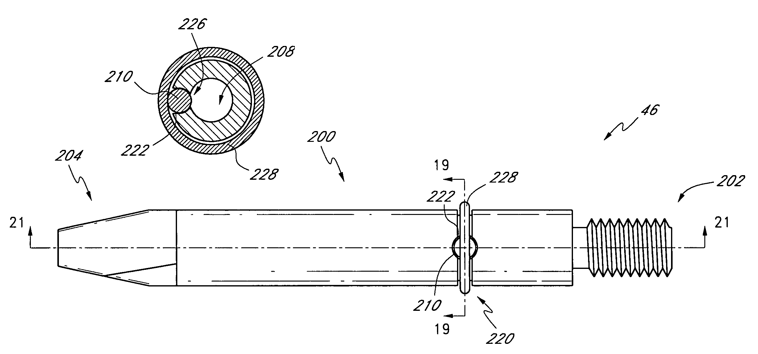
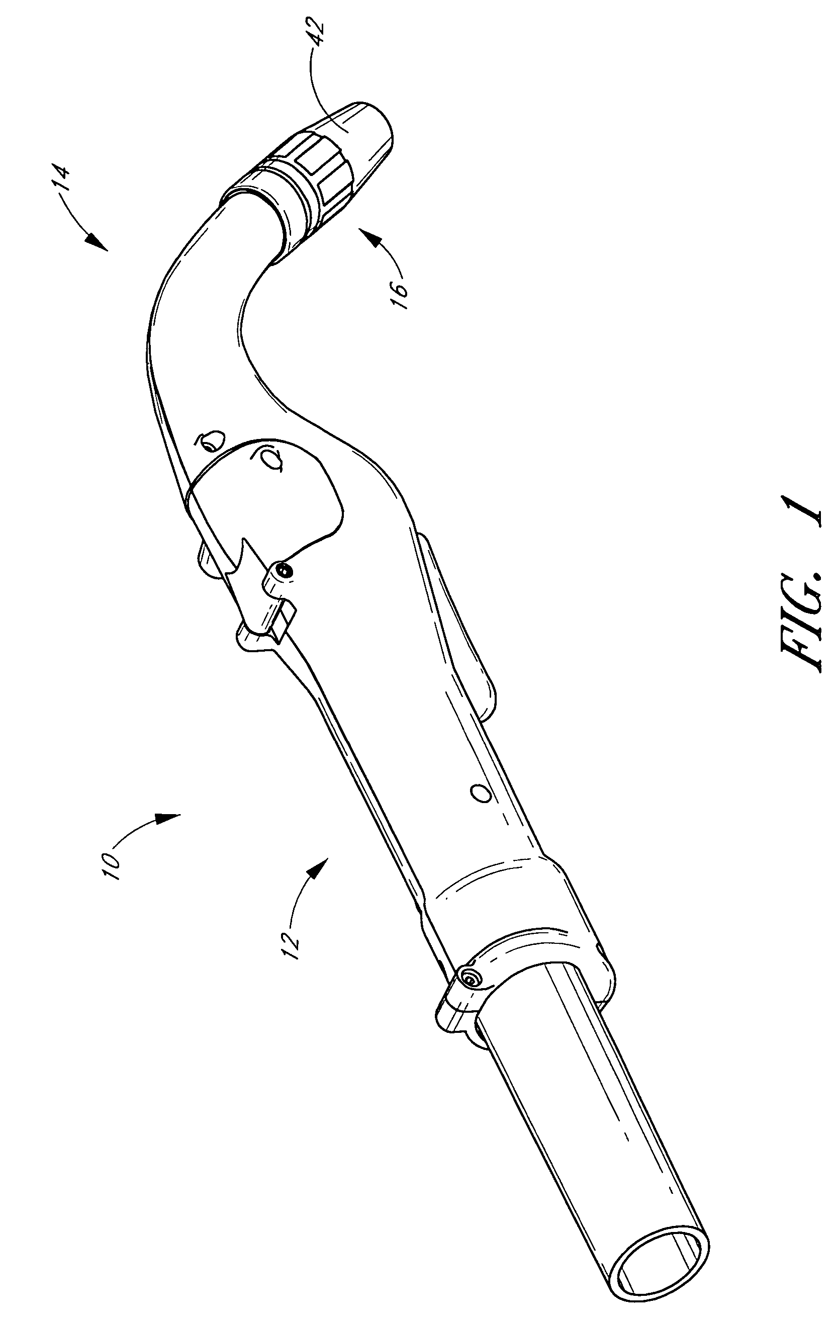
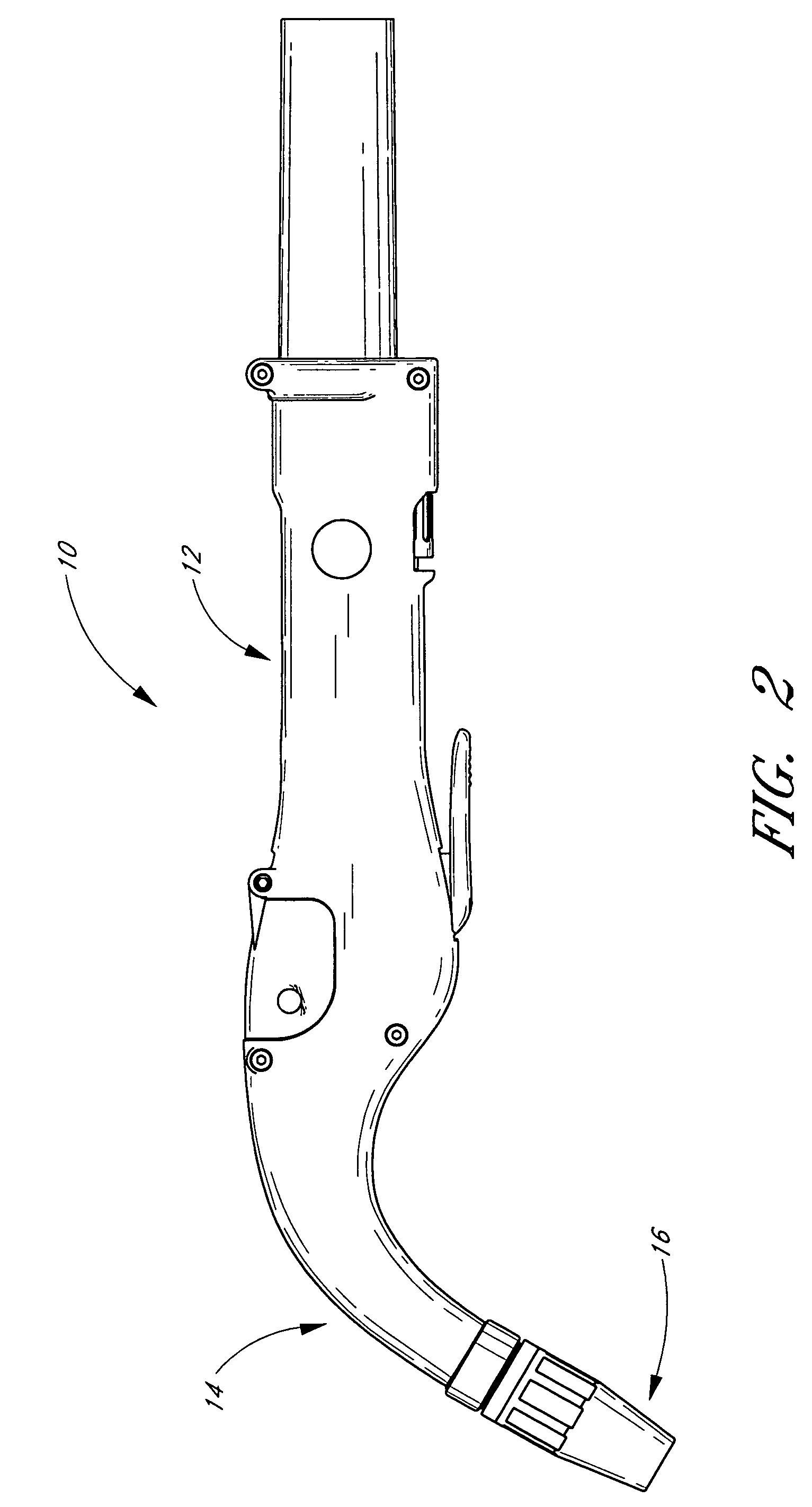
[0052]To enhance understanding of one embodiment of a contact tip, contact tips are discussed in connection with illustrative welding guns shown in FIGS. 1-17. However, unless explicitly claimed, the welding gun embodiments are not to be considered part of the claimed invention, and those of skill in the art will appreciate that the contact tip can be used in connection with virtually any type of welding gun. Accordingly, some embodiments of contact tips shown in FIGS. 18-32 will be described first, after which some embodiments of contact tips in combination with welding guns as shown in FIGS. 1-17 will be described.

I. Contact Tips

[0053]While embodiments of the invention are described below in connection with particular welding guns, it should be noted that other embodiments of the invention can comprise, or be incorporated or implemented in, a wide variety of welding systems. The particular features and advantages associated with the welding guns described below may or may not be a...


PUM

PropertyMeasurementUnit
diameteraaaaaaaaaa
diameteraaaaaaaaaa
diameteraaaaaaaaaa

Abstract

A contact tip for a welding gun includes an elongate body having a first end, a second end, and a first opening extending longitudinally between the first end and the second end. The elongate body has an outer surface and an inner surface. The elongate body has a second opening extending radially through a side portion of the elongate body between the outer surface and the inner surface. At least a portion of the second opening is configured to support a contact element. A contact element is configured to be supported within at least a portion of the second opening of the elongate body and extend at least partially into the first opening of the elongate body. A retention member is configured to couple the contact element with the elongate body.

Description

PRIORITY INFORMATION[0001]This application is based on and claims priority to U.S. Provisional Patent Application No. 60 / 559,564 (filed Apr. 5, 2004), the entire contents of which are hereby expressly incorporated by reference herein and made a part of this specification.BACKGROUND OF THE INVENTION[0002]1. Field of the Invention[0003]This invention relates to welding guns and contact tips for welding guns and, in particular, to a MIG welding gun with a contact tip.[0004]2. Description of the Related Art[0005]A metal inert gas (MIG) welding gun generally comprises a handle, a wire feed mechanism, and a torch barrel. A push-pull MIG welding gun can also include a motor. The welding gun typically also includes a gas tube and a cooling fluid tube for supplying gas and cooling fluid to the tip of the torch barrel. There are three general types of welding guns: pistol grip, goose neck and in-line welding guns. In a pistol grip gun, a motor can be located below a wire feed mechanism and ca...

Claims


Application Information

Patent Timeline
Patent Type & Authority Patents(United States)
IPC IPC(8): B23K9/28B23K9/24B23K9/29
CPCB23K9/295
Inventor KENSRUE, MILO M.
Owner M K PRODS
Why Eureka
Try Eureka