

Electronic wearable device
a wearable device and electronic technology, applied in the direction of antenna details, slot antennas, antennas, etc., can solve the problems of not being able to use described structures in metal-covered devices, unable to incorporate antennas into wearable devices, and unable to use conductive materials in the device housing
- Summary
- Abstract
- Description
- Claims
- Application Information
AI Technical Summary
Benefits of technology
Problems solved by technology
Method used
Image

Examples
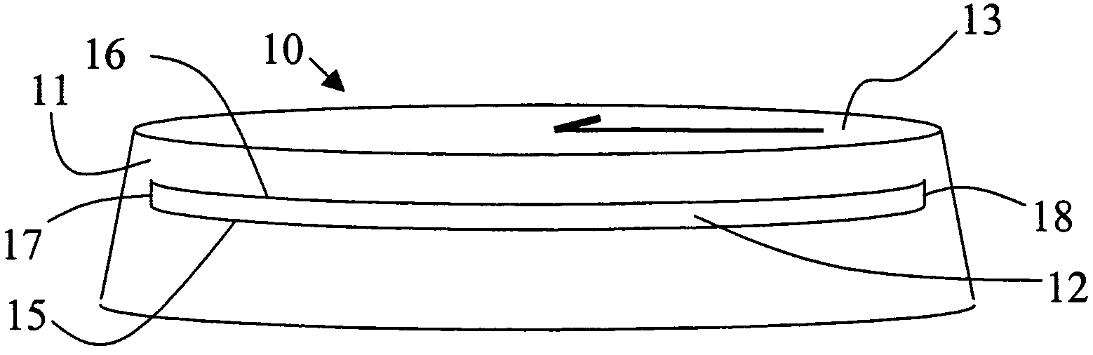
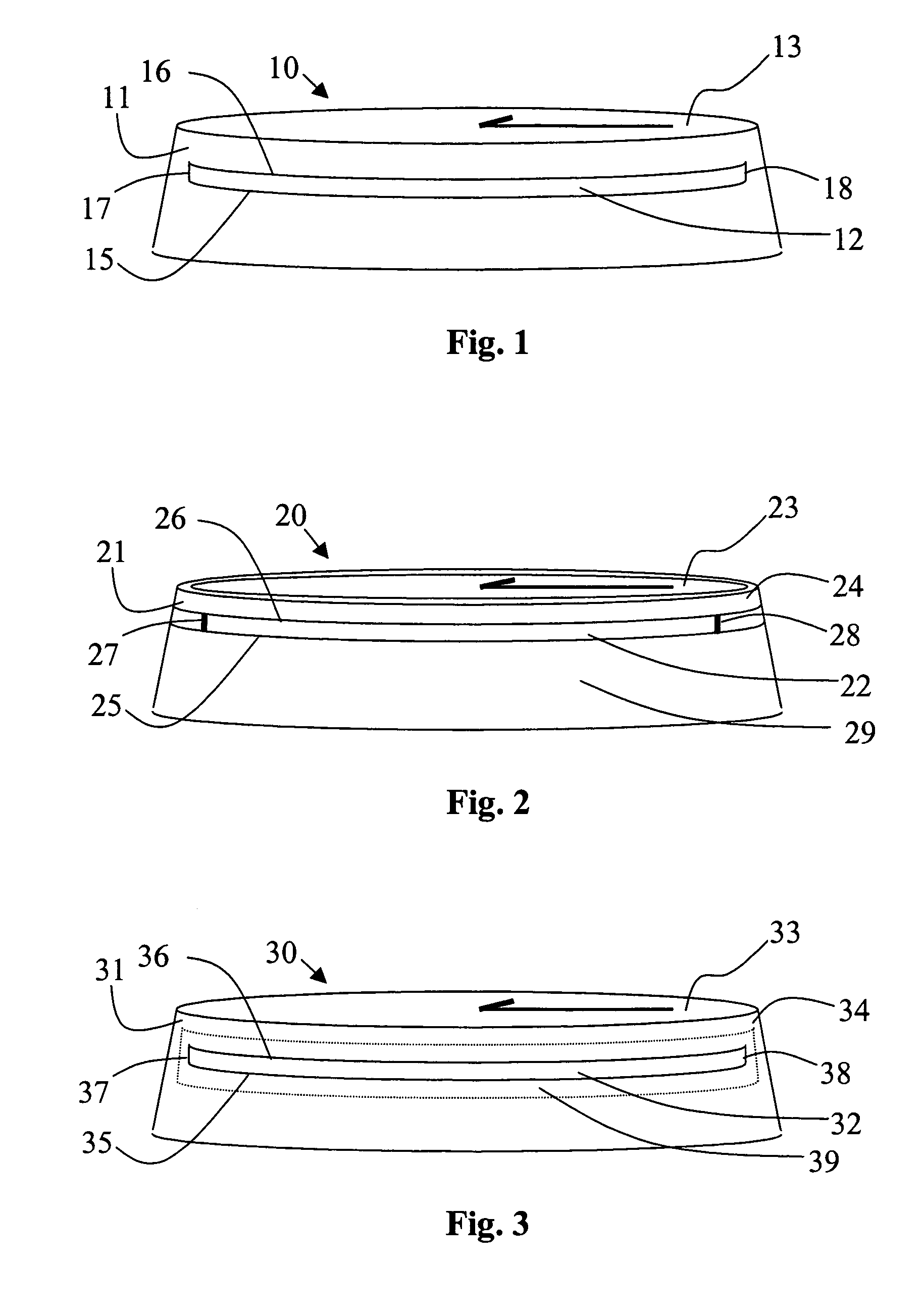
first embodiment
[0036] shown in FIG. 1, the cover 11 is essentially entirely made of conductive material, whereby a slot 12 is fabricated directly to the cover. The slot 12 can be an opening having a length relative to the desired wavelength, on the brim of the cover 11. Longitudinally oriented boundaries of the slot 12 are denoted with reference numerals 15 and 16 and transverse boundaries with reference numerals 17 and 18. The slot 12 can be formed simply by forming a cut to the cover material, for example, by sawing, drilling or chamfering.
second embodiment
[0037] shown in FIG. 2, the cover 21 comprises at least two separate parts 24, 29 (slot-forming members), which are attached together in order to form a slot 22 between the parts. A particularly advantageous embodiment is achieved by providing a first cover part 29 forming the first boundary 25 of the slot 22, and optionally also the extremities 27, 28 of the slot. The slot 22 is completed by providing the second boundary 26 in the form of second cover part 24, such as a separate conductive plate, ring, rod or equivalent onto the first cover part 29. The second cover part can be a special-purpose element or a part of the dial portion of the device, for example, a bezel or another member which is used for mounting a glass, a window or a display to the device. The electrical contact of the plate or ring with the first cover part has to be assured by sufficient clamping of the parts and / or by using a proper contacting substance. The slot-forming members 29, 24 can also be fastened to e...
third embodiment
[0038] illustrated in FIG. 3, the cover 31 is partly made of first material 34 and partly of second material 39 (or a plurality of first and second materials). The slot is formed in the second material portion 39 of the cover, the second material portion being electrically conductive. The second material can be in the form of a plate, film or foil, which is preferably attached on the outer surface of the cover. In FIG. 3, the slot 32 is formed on a narrow foil 39, which is applied on the outer surface of the first material portion 34. The first material portion can also be essentially entirely coated with second material, into which the slot 32 is formed. This embodiment allows a slot antenna being formed also on devices which have a mainly dielectric housing (dielectric first material portion 34) made of plastic, for example. The second material portion of the cover may be brought onto the first material, for example, by conventional metallization techniques, laminating, glueing, v...
PUM
 Abstract
Description
Claims
Application Information