Display device of focal angle and focal distance in iris recognition system
a technology of iris recognition and display device, which is applied in the field of iris recognition system, can solve the problems of user inconvenience, difficult to catch more accurate iris images, and pointless to say that the user would feel uncomfortabl
- Summary
- Abstract
- Description
- Claims
- Application Information
AI Technical Summary
Benefits of technology
Problems solved by technology
Method used
Image
Examples
first embodiment
[0078]Besides what have been discussed before, the present invention is also advantageous for securing more space in a low part of the inside of the camera because the LED 430 is located at the rear side of the hot mirror 410, that is, back of the hot mirror 410.
[0079]A second preferred embodiment of the present invention is now explained as follows.
[0080]FIG. 8 is a front view of an optical system unit explaining a method and apparatus for adjusting a focal angle according to the second preferred embodiment of the present invention;
[0081]Most part of the second embodiment of the present invention is pretty same with the first embodiment except that the second embodiment includes the camera lens 402b for the iris recognition camera 402, the hot mirror 410, and the LED 430 for outputting a light necessary for adjusting the focal angle. Especially, the LED 430 is disposed at the lower part (i.e., the bottom space of the lens) of the hot mirror 410, and light transmitting matter 440 is...
second embodiment
[0084]Thusly configured system also yields the same effect with the present invention.
[0085]In addition, the second embodiment of the present invention depicted in FIGS. 6 and 8 is advantageous in that it shortens the length of the tube in the iris recognition camera by putting the LED 430 on the lower part of the hot mirror 410, that is, the bottom space of the lens.
[0086]As aforementioned, the device for adjusting the focal angle in the iris recognition system according to the present invention uses three iris recognition camera lens 402b so the light transmission distance to the reflection mirror is relatively long. Moreover, because of the long distance between the LED and the lends, when the user moves away from the front part of the lens, the user cannot see the LED light or even if he sees, he can see only blurred LED light. This explains why the present embodiment took the configuration that enables to lead and guide the user to adjust the focal angle more conveniently simpl...
third embodiment
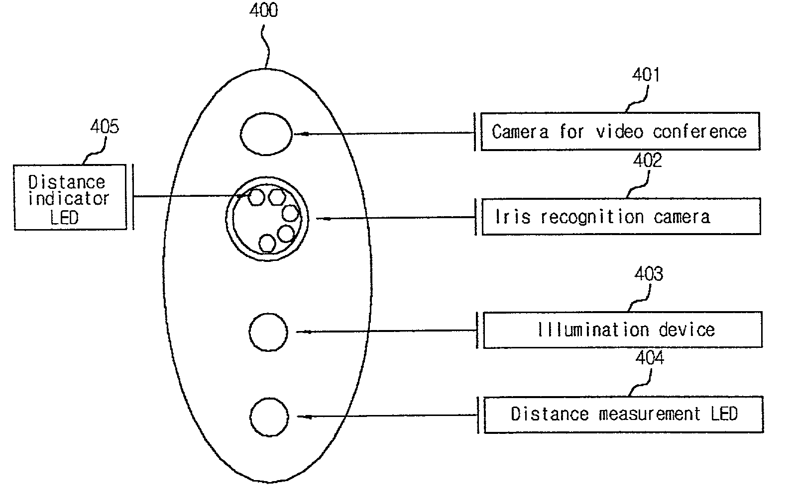
[0092]FIG. 9 is a diagram explaining the present invention.
[0093]Referring to FIG. 9, the main body of the iris recognition device for a video conference 400 according to the third embodiment of the present invention is mounted with the camera for a video conference 401, the iris recognition camera 402, the illumination device 403, and the distance measurement sensor (LED) 404.
[0094]Further, a distance indicator 405 for indicating the user's present position can be mounted at the inside of the iris recognition camera 402 for
[0095]Particularly, the camera for a video conference 401 is used for acquiring images of the user, especially his face, participating in the video conference. The iris recognition camera 402 is used for acquiring the user's eye images that are eventually used for recognizing the user's iris. In addition, the illumination device 403 provides an illumination necessary for photographing iris images to be recognized. The distance measurement illuminator 404 is used ...
PUM
 Abstract
Description
Claims
Application Information
 - R&D
- Intellectual Property
- Life Sciences
- Materials
- Tech Scout
- Unparalleled Data Quality
- Higher Quality Content
- 60% Fewer Hallucinations
Browse by: Latest US Patents, China's latest patents, Technical Efficacy Thesaurus, Application Domain, Technology Topic, Popular Technical Reports.
© 2025 PatSnap. All rights reserved.Legal|Privacy policy|Modern Slavery Act Transparency Statement|Sitemap|About US| Contact US: help@patsnap.com


