
CDMA device with automatic bit rate allocation

Active Publication Date: 2007-09-18
QWEST
View PDF3 Cites 0 Cited by
  • Summary
  • Abstract
  • Description
  • Claims
  • Application Information

AI Technical Summary

Benefits of technology

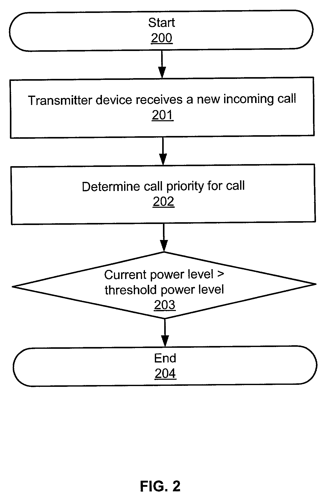
[0007]The present invention advances the art by providing a CDMA transmitter device with bit rate control logic that dynamically adjusts bit rates allocated to new incoming calls and currently active calls based on the current power level of the device and a call priority for the currently active calls and the incoming calls. Advantageously, by looking at the power level of the transmitter device as well as the call priority for the active and incoming calls, the bit rate control logic accounts for the available capacity of the device, maximizes the number of calls handled before call blocking is implemented, and maintains quality of service according to a class of service subscribed to by customers of the service provider.
[0008]According to one aspect of the present invention, a CDMA transmitter comprising base station control logic, call priority logic and bit rate allocation is provided. The base station control logic is configured to determine the current power level of the base station based on a number of currently active calls in the base station. The call priority logic is configured to determine a call priority for new incoming calls based on a class of service for the new incoming calls. The bit rate allocation logic is configured to automatically allocate bit rates to the new incoming calls based on the current power level and the call priority and to adjust bit rates allocated to currently active calls based on the current power level and the call priority to prevent call blocking and maintain operation of the transmitter at or below a maximum operating power.

Problems solved by technology

Each channel requires power to transmit its bit stream, which also generates noise for other channels in the same band.
Therefore, the power level of any bit stream has a direct impact on the system's capacity and the system is said to be interference limited.
Such call-blocking, however, is generally undesirable as it has the obvious disadvantage of dissatisfied customers.
Unfortunately, this method automatically lowers bit rate allocations to calls regardless of other factors for the call, such as class of service.

Method used


Image

  • CDMA device with automatic bit rate allocation
  • CDMA device with automatic bit rate allocation
  • CDMA device with automatic bit rate allocation

Examples


Embodiment Construction

CDMA Transmitter Device and Operation FIGS. 1-2

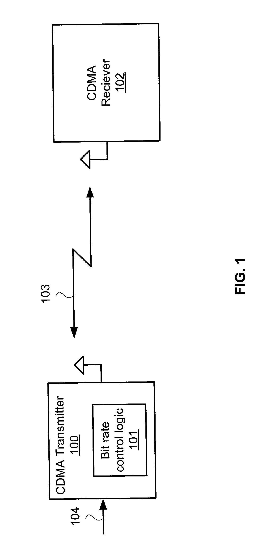
[0018]FIG. 1 depicts a CDMA transmitter 100, a communications signal 104, an RF CDMA signal 103, and CDMA receiver 102. The CDMA transmitter 100 includes bit rate control logic 101. The communications signal 104 could be any signal, such as the signal received from a network switching system. The RF CDMA signal 103 could be a conventional CDMA signal comprising the modulated communications signal 104 with intermediate and radio frequencies.

[0019]The CDMA transmitter 100 transmits the RF CDMA signal 103 to the CDMA receiver 102. The CDMA transmitter 100 could be any CDMA device configured with the bit rate control logic 101. Some examples of the CDMA transmitter 100 include without limitation, a CDMA base station and a CDMA handset device.

[0020]CDMA is a spread spectrum digital technology that assigns a unique identifying code to all calls and then transmits combined call signals over the same broad frequency spectrum. In the CDMA transm...


PUM


Abstract

CDMA transmitter device including bit rate control logic that dynamically adjusts bit rates allocated to new incoming calls and currently active calls based on the current power level of the transmitter device and a call priority for the currently active calls and the incoming calls. The bit rate control logic uses the current power level of the transmitter device and the call priority to allocate lower bit rates to lower priority calls and higher bit rates to higher priority calls to maintain operation of the transmitter device at or below a maximum operating power level.

Description

FIELD OF THE INVENTION[0001]The invention is related to the field of wireless communication services, and in particular, to a Code Division Multiple Access transmitter device that dynamically controls the bit rates allocated to calls based on a power level of the transmitter device and call priority.BACKGROUND OF THE INVENTION[0002]Code Division Multiple Access (“CDMA”) is a digital technology commonly used in wireless communication systems. In a CDMA system, a CDMA device, such as a base station, transmits a CDMA signal to numerous communication devices, such as wireless CDMA handsets. CDMA is a “spread spectrum” technology that assigns a unique code to all bits, transmits a scrambled CDMA signal of encoded bits, and reassembles the bits in their original format.[0003]In a CDMA signal, the individual calls are not separated based on frequency or time, but are spread across an entire frequency band. Each individual call is encoded with a unique pseudo random sequence. The CDMA devic...

Claims


Application Information

Patent Timeline
IPC IPC(8): H04B7/216H04J13/00H04B7/005H04L1/00
CPCH04L1/0002H04L1/0017H04W52/267H04W52/281H04W52/288
Inventor SCHWENGLER, THOMASAREND, BRIAN LOUIS
Owner QWEST
Learn More