Reversible penetrating machine with a differential air distributing mechanism

a differential air distribution and penetrating machine technology, applied in drilling machines and methods, portable percussive tools, constructions, etc., can solve problems such as unneeded assembly, achieve the effects of reducing manufacturing and maintenance costs, preventing any reliability problems of valves, and eliminating springs

Inactive Publication Date: 2007-09-25
SPEKTOR ENG
View PDF17 Cites 3 Cited by
  • Summary
  • Abstract
  • Description
  • Claims
  • Application Information

AI Technical Summary

Benefits of technology

[0012]The invention offers a reversible penetrating machine with a pneumatically controlled differential air distributing mechanism that is characterized by significantly higher efficiency, reliability, and reduced manufacturing and maintenance costs. This is achieved in part by eliminating the failure-prone springs in the differential air distributing mechanism of the previous design with newly designed pneumatically controlled differential air distributing mechanism. Elimination of the springs prevents any reliability issues with the valves and reduces the cost of the machine.
[0014]Another aspect of the invention is the elimination of the relief valve O-ring, which together with the elimination of the springs, allows a decrease in the air pressure in the reduced (low) pressure line, improving the performance of the machine and also providing an opportunity for further simplification of the machine.
[0016]Another aspect of the invention is the possibility of modifying the machine for special applications. In this machine the rear valve chest, the relief valve, and the stepped adapter can be replaced with a flange that has appropriate air ducts. In this case the manufacturing and maintenance cost of the machine is reduced while the performance of the machine in certain working conditions is not compromised.
[0017]One more aspect of the invention is the significant reduction of the contact surface of the machine with the medium (soil), resulting in a respective reduction of the friction between the machine and the medium (soil) during operation. This is achieved by an appropriate enlargement of the diameter of the chisel and transfer of the guiding functions of the machine from its tubular body to the stabilizers, while preventing the tubular body from contacting the medium (soil), thereby causing an improvement in the performance of the machine.

Problems solved by technology

This assembly became unneeded with the elimination of the spring that loads the stroke control valve.

Method used


Image

  • Reversible penetrating machine with a differential air distributing mechanism
  • Reversible penetrating machine with a differential air distributing mechanism
  • Reversible penetrating machine with a differential air distributing mechanism

Examples


Embodiment Construction

General Description

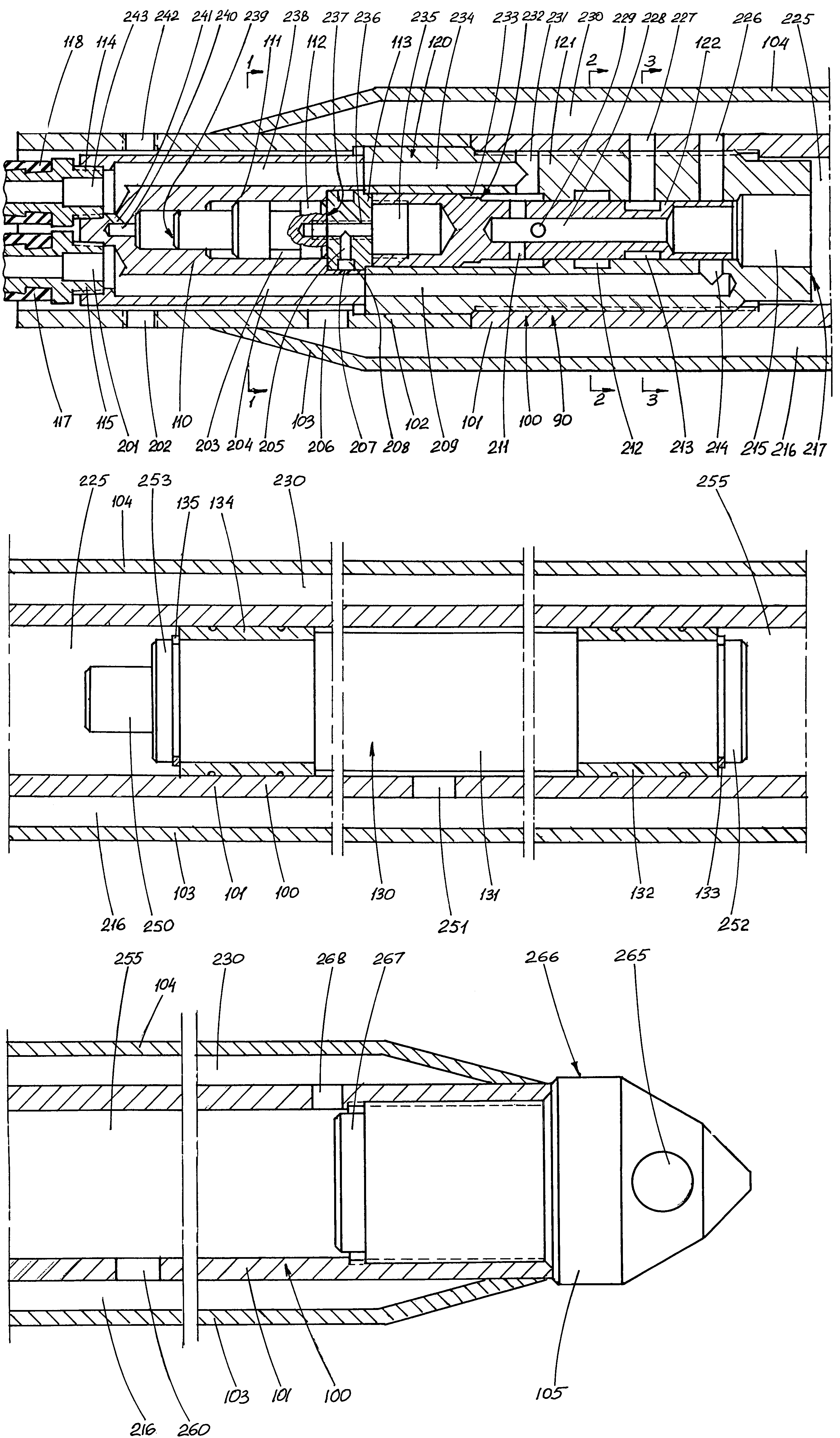
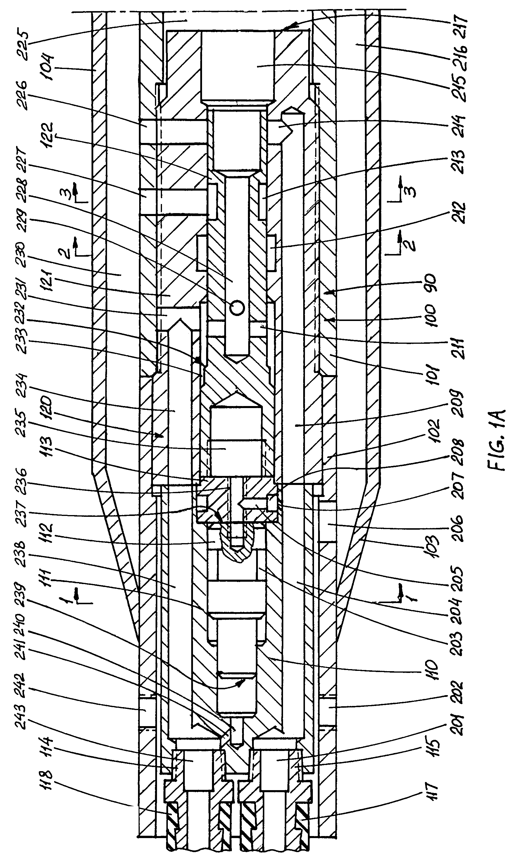
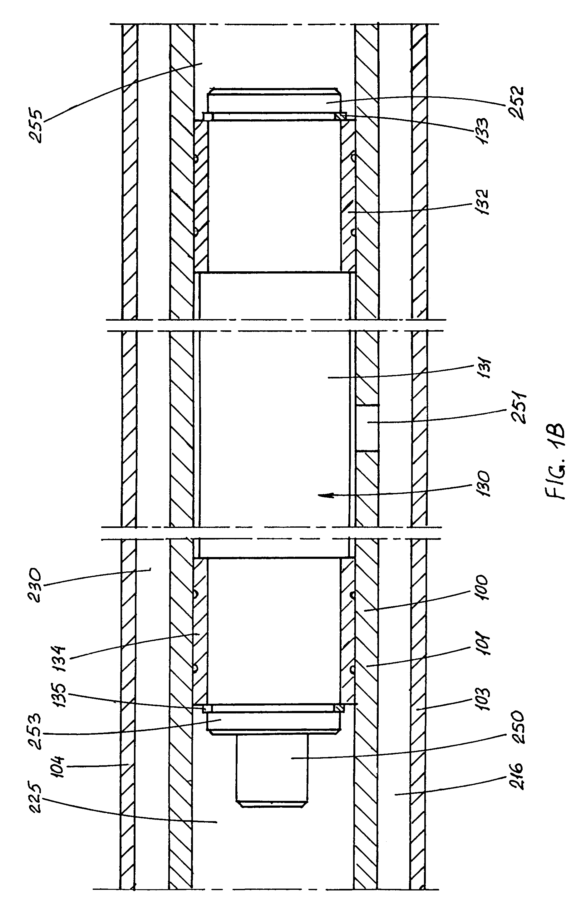
[0035]As shown in FIGS. 1A, 1B, and 1C, a reversible penetrating machine 90 with a pneumatically controlled differential air distributing mechanism according to the invention includes, as major assemblies, an elongated housing assembly 100 comprising a tubular housing (tube) 101, a protective sleeve 102, longitudinal stabilizers 103 and 104, and a chisel 105 rigidly secured by a threaded joint to the front part of tube 101; a striker assembly 130 disposed for reciprocation within tube 101; a pneumatically controlled differential air distributing mechanism comprising a front valve chest assembly 120 rigidly secured by a threaded joint to the rear part of tube 101; and a rear assembly 120. The air distributing mechanism controls the flow of the compressed air causing reciprocation of striker assembly 130. Thread-locking means are used to prevent loosening of threaded joints of tube 101 with front valve chest 121 as well as with chisel 105.

[0036]As FIGS. 1A, 1B, 1C a...


PUM


Abstract

The invention represents a new design of a reversible penetrating machine (90) with a pneumatically controlled differential air distributing mechanism. This design eliminates the springs, the rear anvil assembly, and several other components found in the prior machine. The chisel and the tail of the machine are also redesigned to eliminate the need of a special attachment in case of retracting a failed machine. In addition, a simplified modification of the machine for special applications is disclosed in which the rear valve chest with associated parts is replaced by a single flange having appropriate air ducts. Finally, the new design of the chisel causes a reduction of the lateral friction between the body of the machine and soil. All this significantly increases the reliability and efficiency of the machine and results in decrease of the related manufacturing and operating cost.

Description

FIELD OF THE INVENTION[0001]The present invention belongs to the group of reversible pneumopercussive soil-penetrating machines used mainly for making underground horizontal holes and driving pipes and cables into these holes. In the mining industry, these machines are used for making ventilation holes as well as for driving explosives into these holes.BACKGROUND OF THE INVENTION[0002]Reversible pneumopercussive soil-penetrating machines have long been known and widely used in the industry of trenchless installation and repair of pipes and cables. These machines basically comprise a tubular body, accommodating in the rear part of it an air distributing mechanism, in front part of it a sharpened chisel, and inside of it a reciprocating striker. The rear part of the chisel represents a front anvil. A tail nut in the rear part of the tubular body secures the interior assembly of the machine, keeping together the related components. A pneumatic hose is concentrically attached to the rea...

Claims


Application Information

Patent Timeline
Patent Type & Authority Patents(United States)
IPC IPC(8): E21B4/14E21B7/26
CPCE21B4/145
Inventor SPEKTOR, MICHAEL B.
Owner SPEKTOR ENG
Why Eureka
Try Eureka