Connector assembly

a connector and assembly technology, applied in the field of connector assemblies, can solve the problems of difficult manufacturing of contact mechanisms, difficult to manufacture and mount connector assemblies,

Inactive Publication Date: 2007-09-25
MATSUSHITA ELECTRIC WORKS LTD
View PDF14 Cites 30 Cited by
  • Summary
  • Abstract
  • Description
  • Claims
  • Application Information

AI Technical Summary

Benefits of technology

[0006]In view of the above problem, the object of the present invention is to provide a connector assembly which can be easily manufactured and be mounted on a substrate even if a pitch of the cables is small.
[0007]A connector assembly in accordance with the present invention comprises a header and a socket. The header has a first terminal array to which a plurality of cables are electrically connectable. The socket is configured to be coupled with the header and it has a second terminal array which comes in contact with the first terminal array when the header is coupled to the socket. The first terminal array has a plurality of first terminals each having a wire terminal for connection with each conductive wire of the cables and a contact for contact with second terminal array. The feature of the present invention resides in that the wire terminals of the first terminal array are arranged in a line, and the contacts of the first terminal array are arranged in two rows in a staggered configuration, and a pitch of the contacts of each row is larger than a pitch of the wire terminals. In the connector assembly of the present invention, because the contacts of the first terminal array are arranged in two rows in a staggered configuration and the pitch of the contacts of each row is larger than that of the wire terminals, the pitch of the contacts of each row becomes large even if the pitch of the wire terminals (namely, the pitch of the cables) is small. So, it is easy to manufacture the connector assembly. Furthermore, because the wire terminals of the first terminal array are arranged in a line, it is possible to solder the conductive wires of the cables to the wire terminals by a length of wire solder at a time. Therefore, it is easy to connect the cables to the first terminal array.
[0008]Preferably, the second terminal array has a plurality of second terminals each having a lead terminal for mounting the socket on a substrate, and the lead terminals of the second terminal array are arranged in two rows in a staggered configuration on both sides of the socket. In this case, a pitch of the lead terminals of each row can be increased, so that it becomes easy to mount the socket on the substrate. Or, each of the lead terminals can be formed larger to increase joint strength between the socket and the substrate and to increase mount reliability. The lead terminals may be arranged in two rows in a staggered configuration on one side of the socket.
[0014]By using this method, it becomes easy to manufacture the header of the connector assembly of the present invention.

Problems solved by technology

Therefore, when a pitch of the cables becomes small, the pitch of the first terminal array and a pitch of the second terminal array, which corresponds to the first terminal array, also become small, and therefore it becomes difficult to manufacture and mount the connector assembly.
Especially, it is difficult to manufacture a contact mechanism for bringing the first terminal array into contact with the second terminal array with a minimum pitch.

Method used


Image

  • Connector assembly
  • Connector assembly
  • Connector assembly

Examples


first embodiment

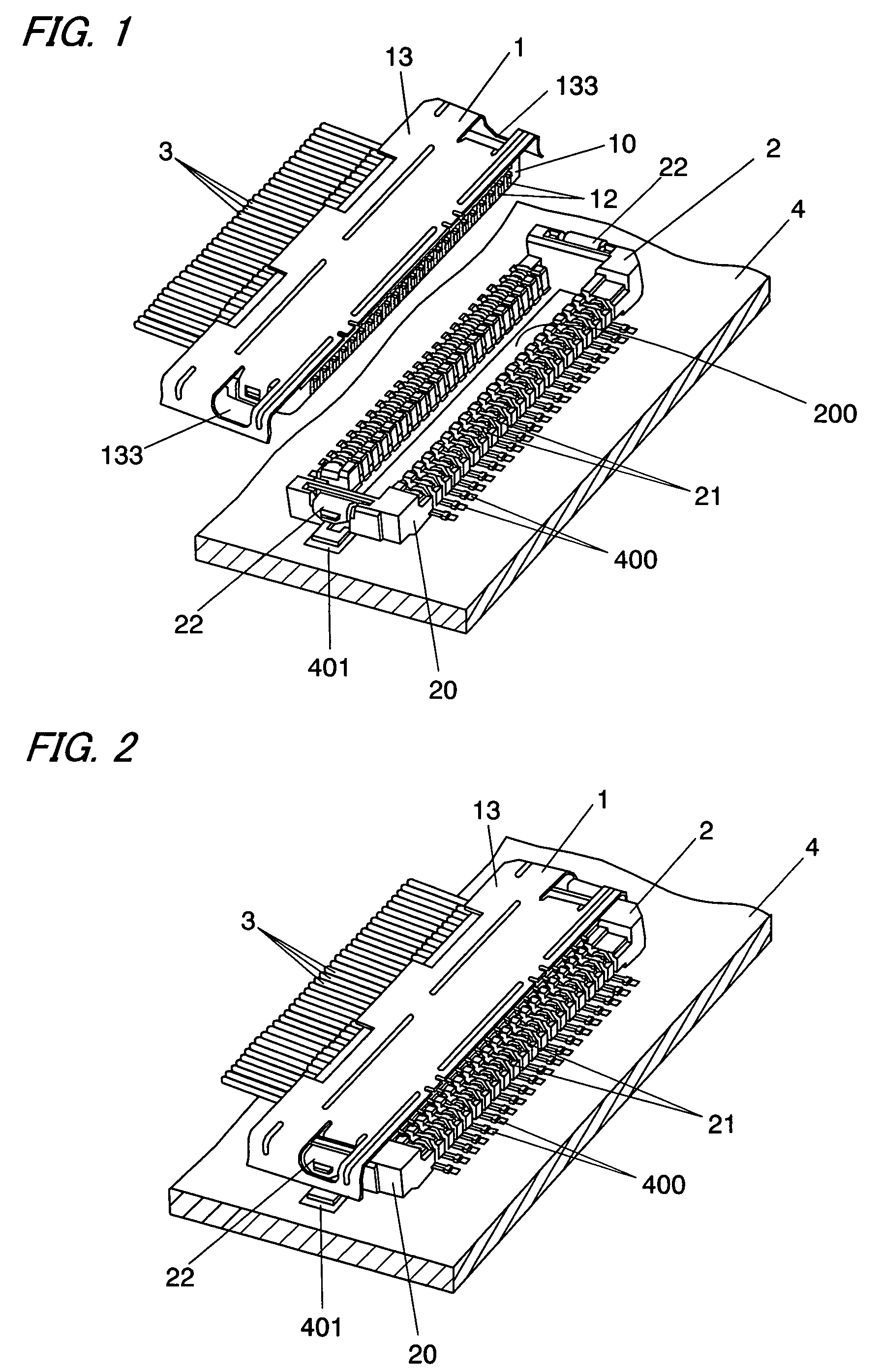
[0040]FIG. 1 shows a connector assembly in accordance with a first embodiment of the present invention. This connector assembly comprises a header 1 to which a plurality of coaxial cables 3 are connectable and a socket 2 configured to be mounted on a printed board 4. The header 1 can be detachably coupled to the socket 2. This connector assembly is for connecting the coaxial cables 3 to an electric circuit (not shown) on the printed board 4 by coupling the header 1 to the socket 2, as shown in FIG. 2.

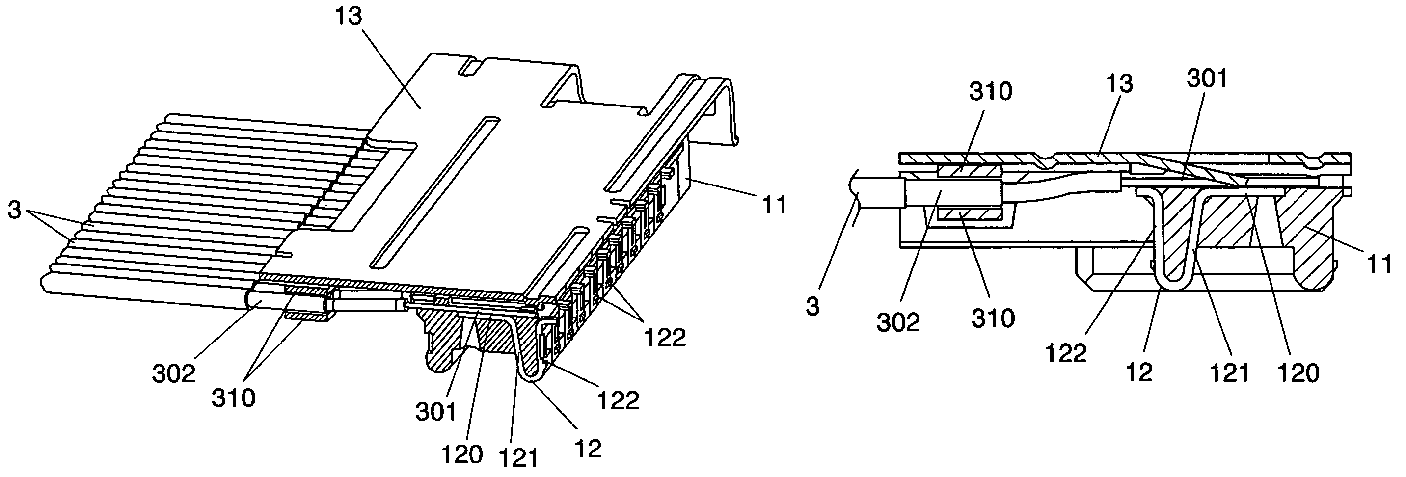
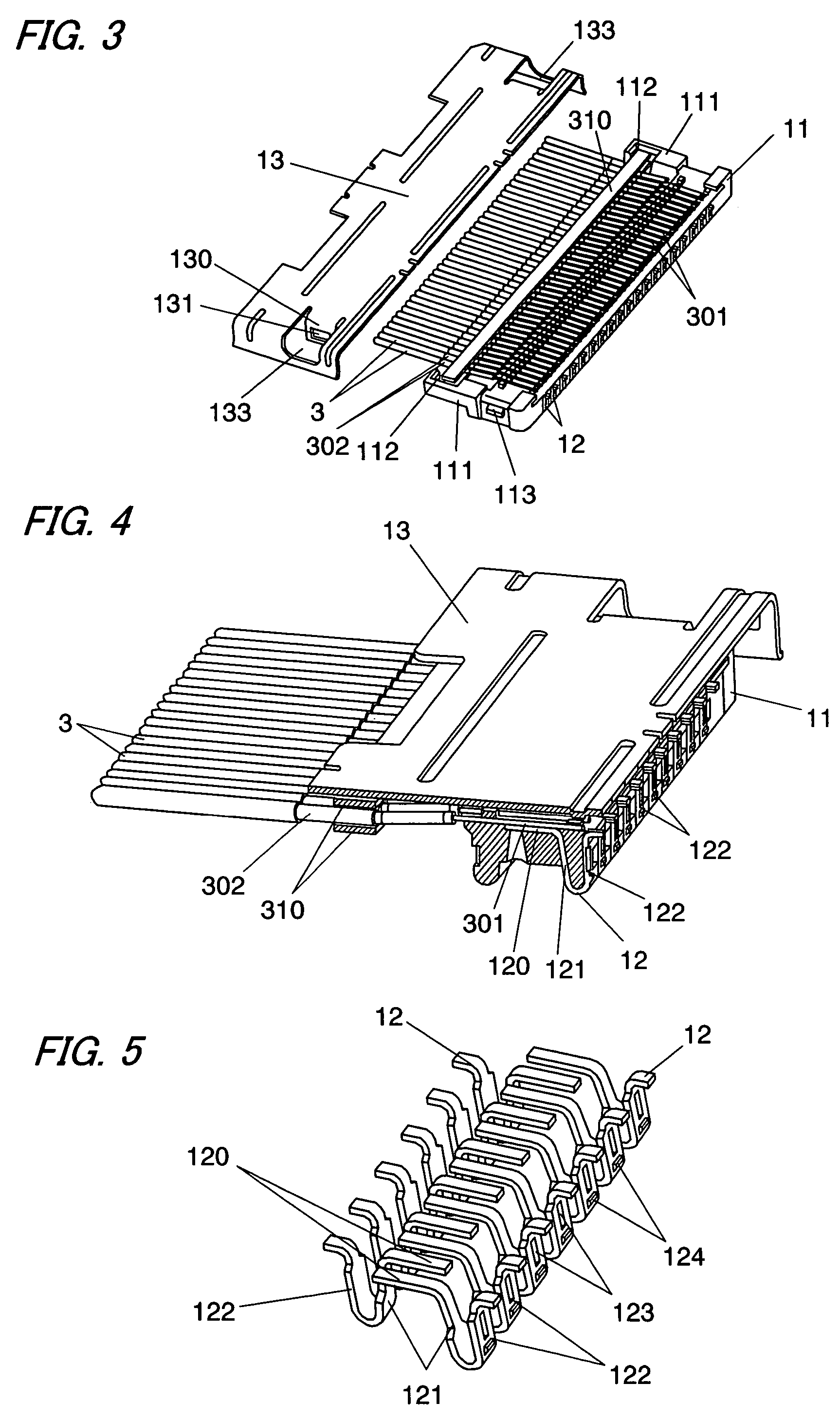
[0041]As shown in FIGS. 3 to 4, the header 1 comprises a rectangular parallelepiped shaped body 11 made of a synthetic resin, a first terminal array (12, 12, . . . ) insert-molded into the body 11 and a shell 13 for covering an upper surface of the body 11 to block electromagnetic noise. The coaxial cables 3 are electrically connected to the first terminal array. As shown in FIG. 5. the first terminal array is composed of a plurality of first terminals 12. Each first terminal 12 is made...

second embodiment

[0051]FIG. 16 shows a connector assembly in accordance with a second embodiment of the present invention. The basic composition of this embodiment is identical to the first embodiment, so the similar part of these embodiments are identified by the same reference character and no duplicate explanation is made here. Although, in the first embodiment, the header 1 was configured to be inserted into the socket 2 vertically with respect to the printed board 4, the header 1 of this embodiment is configured to be inserted into the socket in parallel with respect to the printed board.

[0052]As shown in FIG. 16, the connector assembly of this embodiment also comprises a header 1 to which a plurality of coaxial cables 3 are connectable, and a socket 2 configured to be mounted on a printed board 4. The header 1 can be detachably coupled to the socket 2. As shown in FIG. 17, the header 1 comprises a body 11 made of a synthetic resin, a first terminal array (12, 12, . . . ) which was insert-molde...


PUM

PropertyMeasurementUnit
conductiveaaaaaaaaaa
lengthaaaaaaaaaa
joint strengthaaaaaaaaaa

Abstract

This connector assembly comprises a header 1 to which a plurality of coaxial cables 3 are connectable and a socket 2 configured to be mounted on a printed board 4. The header 1 can be detachable coupled to the socket 2. The header 1 has a first terminal array 12 to which the coaxial cables 3 are electrically connectable. The socket 2 has a second terminal array 21 which makes contact with the first terminal array 12 when the header 1 is coupled to the socket 2. The first terminal array has a plurality of first terminals each having a wire terminal 120 for connection with each conductive wire of the cables and a contact 122 for contact with the second terminal array. The feature of the present invention resides in that the wire terminals 120 are arranged in a line, and the contacts 122 of the first terminal array are arranged in two rows in a staggered configuration, and a pitch of the contacts 122 of each row is larger than a pitch of the wire terminals 120.

Description

TECHNICAL FIELD[0001]The present invention relates to a connector assembly for electrical connection between cables and a substrate.BACKGROUND ART[0002]Japanese Non-examined Patent Publication No. 11-307187 discloses a connector assembly for electrical connection between cables and a substrate.[0003]This connector assembly comprises a header to which a plurality of cables are electrically connectable and a socket configured to be mounted on a substrate.[0004]The header can be coupled to the socket. The header has a first terminal array to which cables are connectable. The socket has a second terminal array which makes contact with the first terminal array when the header is coupled to the socket. The second terminal array includes lead terminals for mounting the socket on the substrate, and the second terminal array is electrically connected to an electric circuit on a substrate through the lead terminals. When the header is coupled to the socket, the first terminal array comes in c...

Claims


Application Information

Patent Timeline
Patent Type & Authority Patents(United States)
IPC IPC(8): H01R12/24H01R12/50H01R43/24H01R12/59H01R12/71H01R12/79H01R43/16
CPCH01R43/16H01R12/598H01R12/79H01R12/712H01R12/716Y10T29/4922H01R43/24
Inventor IIDA, MITSURUTANAKA, HIROHISAJOUNEN, KENJIYOSHIOKA, KOUSUKE
Owner MATSUSHITA ELECTRIC WORKS LTD
Why Eureka
Try Eureka