Thermoelectric power generation systems

a technology of power generation system and thermoelectric device, which is applied in the manufacture/treatment of thermoelectric devices, machines/engines, lighting and heating apparatus, etc., can solve the problems of not necessarily optimizing system performance for today's applications, and the use of thermoelectric power generation has been limited, so as to increase the efficiency of the system, increase the power density, and increase the effect of interes

Inactive Publication Date: 2007-09-25
GENTHERM INC
View PDF89 Cites 88 Cited by
  • Summary
  • Abstract
  • Description
  • Claims
  • Application Information

AI Technical Summary

Benefits of technology

[0010]New heterostructure thermoelectric, quantum tunneling, very thin plated, and deposited thermoelectric materials operate at substantially higher power densities than typical of the previous bulk materials and offer the potential for higher system efficiency. In addition, recent advancements in thermoelectric (TE) material and systems have renewed interest in the potential use of TEs for power generation. The inherent qualities of TE systems, few if any moving parts, quiet operation and the prospects of both environmental friendliness and waste power recovery have increased further the interest.
[0011]Successful operation of thermoelectric devices with high power density requires high heat transfer rates both on the cold and hot side of TE Modules. One way to achieve this is through rotary designs that lend themselves to high fluid flow rates, and hence, high thermal power throughput. In one preferred embodiment, rotary systems in which a portion of the heat exchanger acts as fan blades, and thereby contributes to working fluid flow, can reduce power into the fan, simplify system design and reduce size.
[0013]Properly designed heat pipes are very efficient and transport large thermal fluxes with very low temperature differential. Some keys to efficient operation are that the liquid return process be efficient and that the entire heat source side be wetted at all times, to make liquid always available to evaporate and carry away thermal power. Similarly, it is important that the cool, sink side does not accumulate liquid since heat pipe working fluids are usually relatively poor thermal conductors. Thus, the sink side should shed liquid efficiently, to maintain effective surface thermal conductivity.
[0014]Power generators that are combined with thermal isolation as described in U.S. patent application Ser. No. 09 / 844,818, entitled Improved Efficiency Thermoelectrics Utilizing Thermal Isolation can further increase performance.

Problems solved by technology

Although it has long been understood that thermoelectric devices can be used to generate power, thermoelectric power generation has been little utilized because the efficiency of present generator design and the power density of such generators are too low.
464-467) that do not necessarily optimize system performances for today's applications.

Method used


Image

  • Thermoelectric power generation systems
  • Thermoelectric power generation systems
  • Thermoelectric power generation systems

Examples


Embodiment Construction

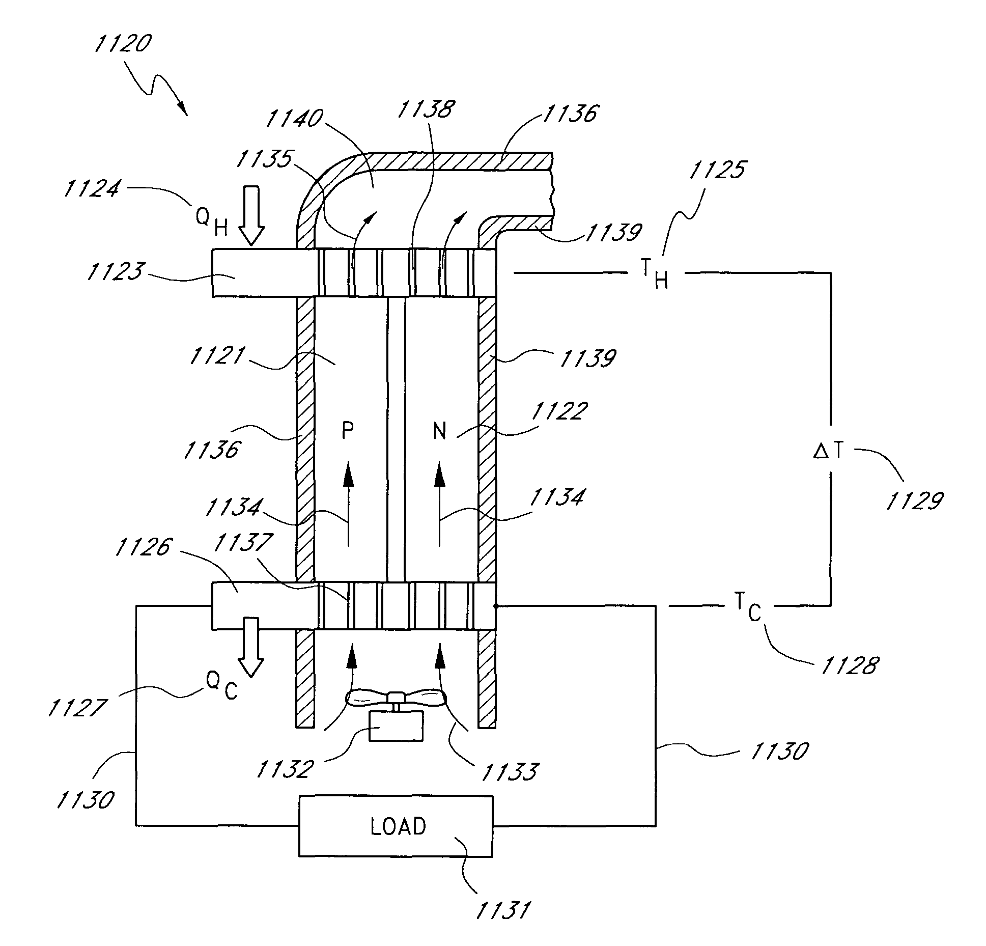
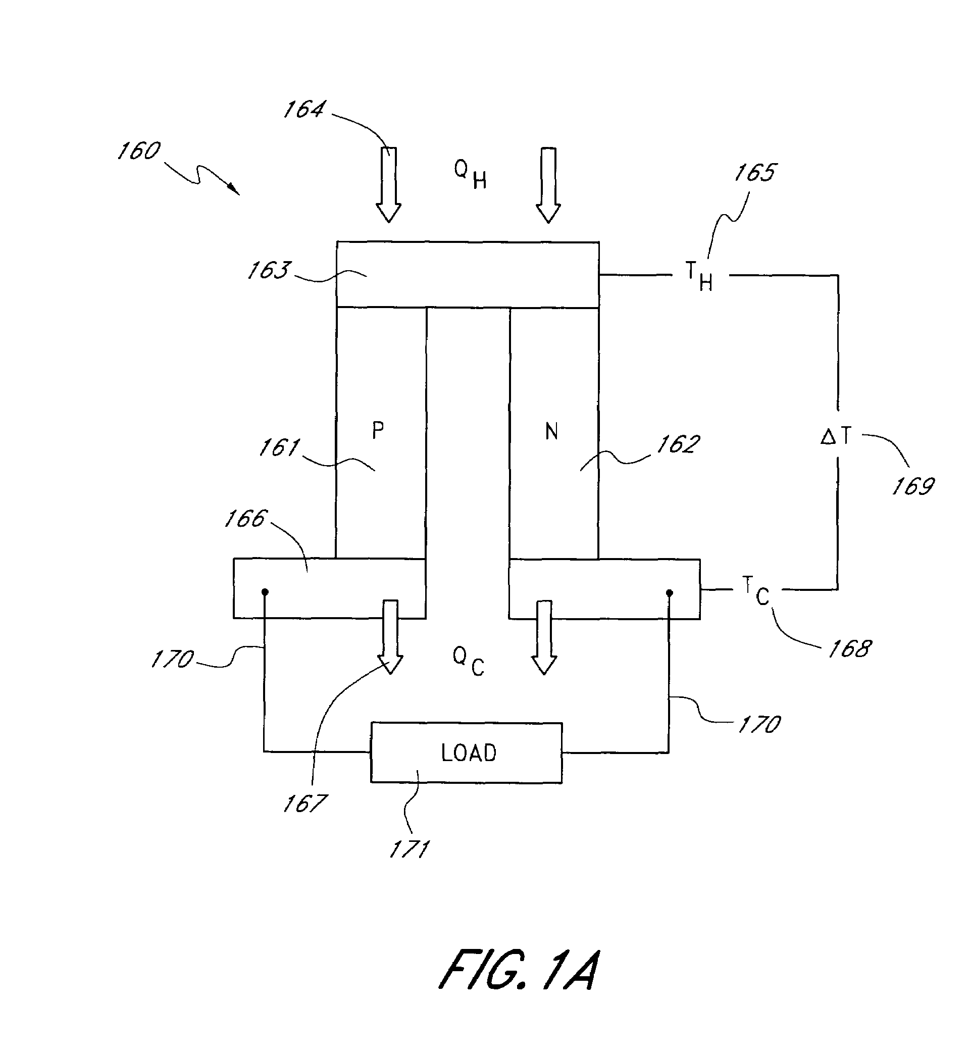
[0053]Power generators are disclosed using new thermodynamic cycles where waste heat from the TEs can be recycled to the hotter side along with added heat. Also disclosed are ways to combine combustion with a TE power generator. Emphasis is placed on factors that influence efficiency, including the effects of hot side and cold side conditions that increase efficiency when used with the new thermodynamic cycles. (Bell, L. E., “Use of Thermal Isolation to Improve Thermoelectric System Operating Efficiency,”Proceedings 21st International Conference on Thermoelectrics, Long Beach, Calif., August 2002 and Bell, L. E., “Increased Thermoelectric System Thermodynamic Efficiency by Use of Convective Heat Transport,”Proceedings 21st International Conference on Thermoelectrics, Long Beach, Calif., August 2002). The source of thermal power (heat) is of special benefit when used for power generation in systems where the available means of eliminating waste heat from the cold side influence stron...


PUM


Abstract

Representative configurations for improved thermoelectric power generation systems to improve and increase thermal efficiency are disclosed.

Description

PRIOR RELATED PROVISIONAL AND PATENT APPLICATIONS[0001]This application is a continuation-in-part of U.S. patent application Ser. No. 10 / 164,656, file Jun. 6, 2002 (now U.S. Pat. No. 6,625,990), which is a continuation-in-part of U.S. patent application Ser. No. 10 / 074,543, filed Feb. 11, 2002 (now U.S. Pat. No. 6,637,210), and a continuation-in-part of U.S. patent application Ser. No. 09 / 971,539 filed Oct. 2, 2001 (now U.S. Pat. No. 6,606,866), and a continuation-in-part of U.S. patent application Ser. No. 09 / 918,999, filed Jul. 31, 2001 (now U.S. Pat. No. 6,598,405) and a continuation-in-part of U.S. patent application Ser. No. 09 / 844,818 (now U.S. Pat. No. 6,539,725) filed Apr. 27, 2001, which related to and claims the benefit of the filing date of prior filed U.S. Provisional Patent Application No. 60 / 267,657, filed Feb. 9, 2001.BACKGROUND OF THE INVENTION[0002]1. Field of the Invention[0003]The present invention relates to the field of power generation using thermoelectric devi...

Claims


Application Information

Patent Timeline
Patent Type & Authority Patents(United States)
IPC IPC(8): H01L35/32B60H1/22F02G1/043F25B21/02F25B27/02F25B33/00H01L35/00H01L35/30H02N11/00
CPCB60H1/2215F02G1/043F25B21/02H01L35/00H01L35/30H01L35/32H02N11/002B60H2001/2275F25B33/00F25B2321/021F28D15/0208F28D15/0233H10N10/00H10N10/17H10N10/13
Inventor BELL, LON E.
Owner GENTHERM INC
Why Eureka
Try Eureka