
Device for monitoring spatial areas

a technology for spatial areas and devices, applied in distance measurement, surveying and navigation, instruments, etc., can solve the problems of people's shoes melting, high susceptibility to failure of known light curtains, and high assembly and method costs, so as to reduce the susceptibility to failure of devices and improve work safety.

Active Publication Date: 2007-09-25
ROCKWELL AUTOMATION
View PDF11 Cites 14 Cited by
  • Summary
  • Abstract
  • Description
  • Claims
  • Application Information

AI Technical Summary

Benefits of technology

[0009]A further advantage of the device according to the invention is the simplicity with which it can be fitted, as only a single emitter and one receiver have to be fitted in proximity to the spatial area to be monitored. Unlike the prior art, it is therefore not necessary to fit a plurality of emitters with reflectors or receivers opposite them along the spatial area to be monitored. With the device according to the invention the emitters and receivers are instead combined in one semiconductor sensor, which can be fitted simply so that a spatial area to be monitored can be comprehensively monitored.
[0011]The use of semiconductor sensors also offers the advantages of large-scale production at low unit cost. Adaptation to the respective application can be achieved by programming the selection unit. Devices according to the invention do not therefore have to be adapted to the respective application at the time of production, so that large numbers of the finished devices can be produced.
[0013]This device is therefore particularly advantageous, if only specific objects, for example people, are to trigger a detection signal in the spatial area to be monitored.
[0018]Further applications relate to automatic door opening systems or door closing units, with which in particular the reduced susceptibility to failure of the device according to the invention is advantageous.

Problems solved by technology

The known light curtains necessitate high assembly and method costs, as a plurality of individual light barriers has to be arranged along the entire monitoring area and housed in correspondingly large housings.
Also the high level of susceptibility to failure of the known light curtains is disadvantageous.
Such failures occur principally in winter, when snow brought into buildings on people's shoes melts and forms small puddles.
Also paper left in the monitoring area of the light curtains can cause incidental reflection and failure of the light curtains.

Method used


Image

  • Device for monitoring spatial areas
  • Device for monitoring spatial areas
  • Device for monitoring spatial areas

Examples


Embodiment Construction

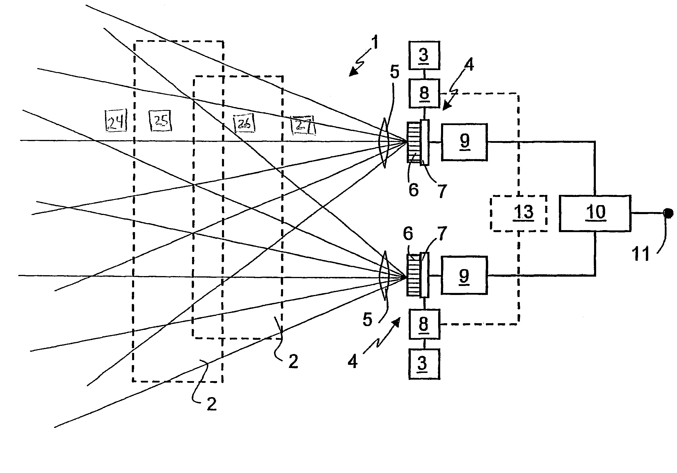
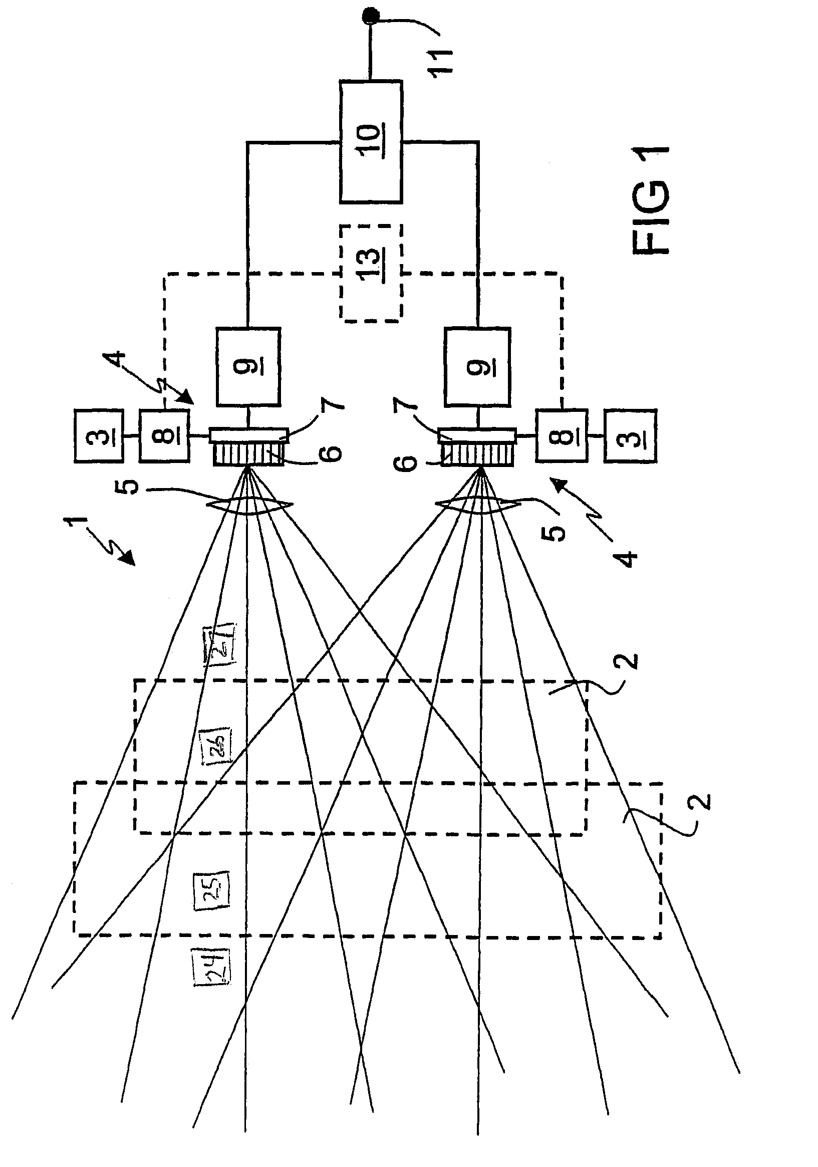
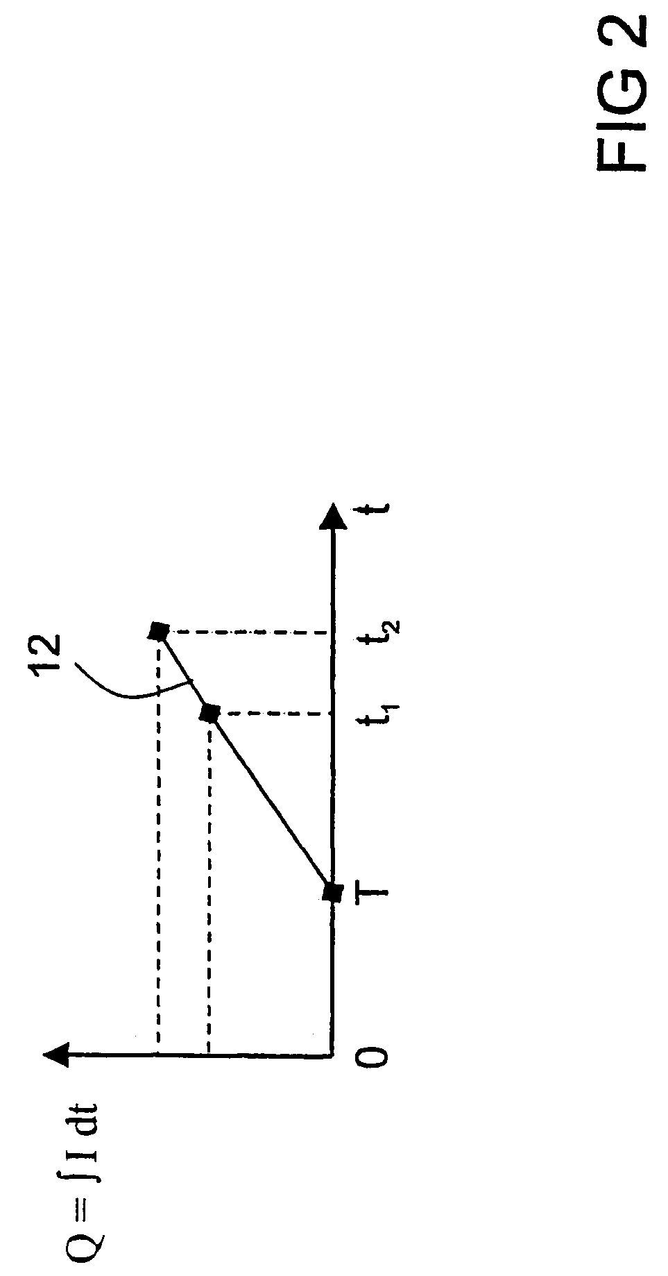
[0028]FIG. 1 shows the monitoring device 1 for monitoring spatial areas 2. The monitoring device 1 has emitters 3, which emit short radiation pulses towards the spatial areas 2 to be monitored. The emitter 3 comprises LEDs or lasers, which preferably emit in the infrared wavelength range. The radiation pulses are reflected back from objects in the spatial areas 2 to the receivers 4. The receivers 4 comprise an optical system 5, by means of which objects in the spatial areas 2 can be mapped onto pixels 6 of a CMOS sensor 7 with short-time integration. The CMOS sensor 7 is a monolithically integrated optoelectronic semiconductor sensor, which was produced using CMOS technology. It should be possible to control each of the individual pixels 6 of the CMOS sensor 7, if required. The pixels 6 of the CMOS sensor 7 each respectively comprise a photodiode and an assigned pixel capacitor, which is charged by exposure of the photodiode when the time measuring window is open. The residual charg...


PUM


Abstract

A monitoring device (1) for spatial areas (2) includes emitters (3) that emit radiation pulses that are reflected by objects located within the spatial areas (2) toward receivers (4). The receivers (4) are connected to a run time determining unit (9) with whose aid a distance image of an object within the spatial areas (2) can be generated. A selection unit (10) evaluates the distance images and generates a detection signal at an output (11) when predetermined distance values occur in the distance images.

Description

BACKGROUND OF THE INVENTION[0001]The invention relates to a device for monitoring spatial areas with an emitter emitting radiation and a receiver receiving the emitted radiation, which is connected to an evaluation unit. The invention also relates to uses for the device.[0002]Such devices are for example known as light curtains. Light curtains are used in numerous fields to safeguard hazard areas or to protect people or objects. They are an industrial mass-produced article. One typical application is personal protection in the working area of production equipment.[0003]Essentially light curtains are a series of individual light barriers lined up along the entire monitoring area. A distinction is made here between passive and active variants. The active variants each comprise emitters with receivers opposite, while the passive variants comprise adjacent emitters and receivers, whereby the light emitted by the receivers is reflected back to the receivers by reflectors arranged opposit...

Claims


Application Information

Patent Timeline
IPC IPC(8): G01C3/08G01S17/10G01S17/04G01S17/894
CPCG01S17/026G01S17/10G01S17/04G01S17/894
Inventor DOEMENS, GUNTERMENGEL, PETER
Owner ROCKWELL AUTOMATION
Learn More