Radiofrequency transmitter and/or receiver

a radiofrequency transmitter and receiver technology, applied in the field of satellite broadcasting devices, can solve the problems of difficult to produce such a synthesizer using current means, and inability to use a conventional device such as the one in fig. 1

Inactive Publication Date: 2007-09-25
INTERDIGITAL MADISON PATENT HLDG
View PDF9 Cites 10 Cited by
  • Summary
  • Abstract
  • Description
  • Claims
  • Application Information

AI Technical Summary

Benefits of technology

[0011]It is an object of the invention to provide a simple solution for a broadband rece

Problems solved by technology

The use of a conventional device such as that in FIG. 1 is not possible for many reason

Method used


Image

  • Radiofrequency transmitter and/or receiver
  • Radiofrequency transmitter and/or receiver
  • Radiofrequency transmitter and/or receiver

Examples


first embodiment

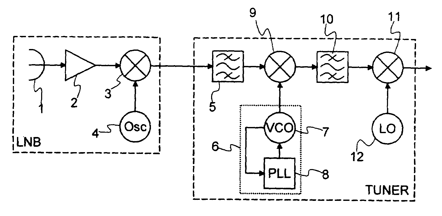
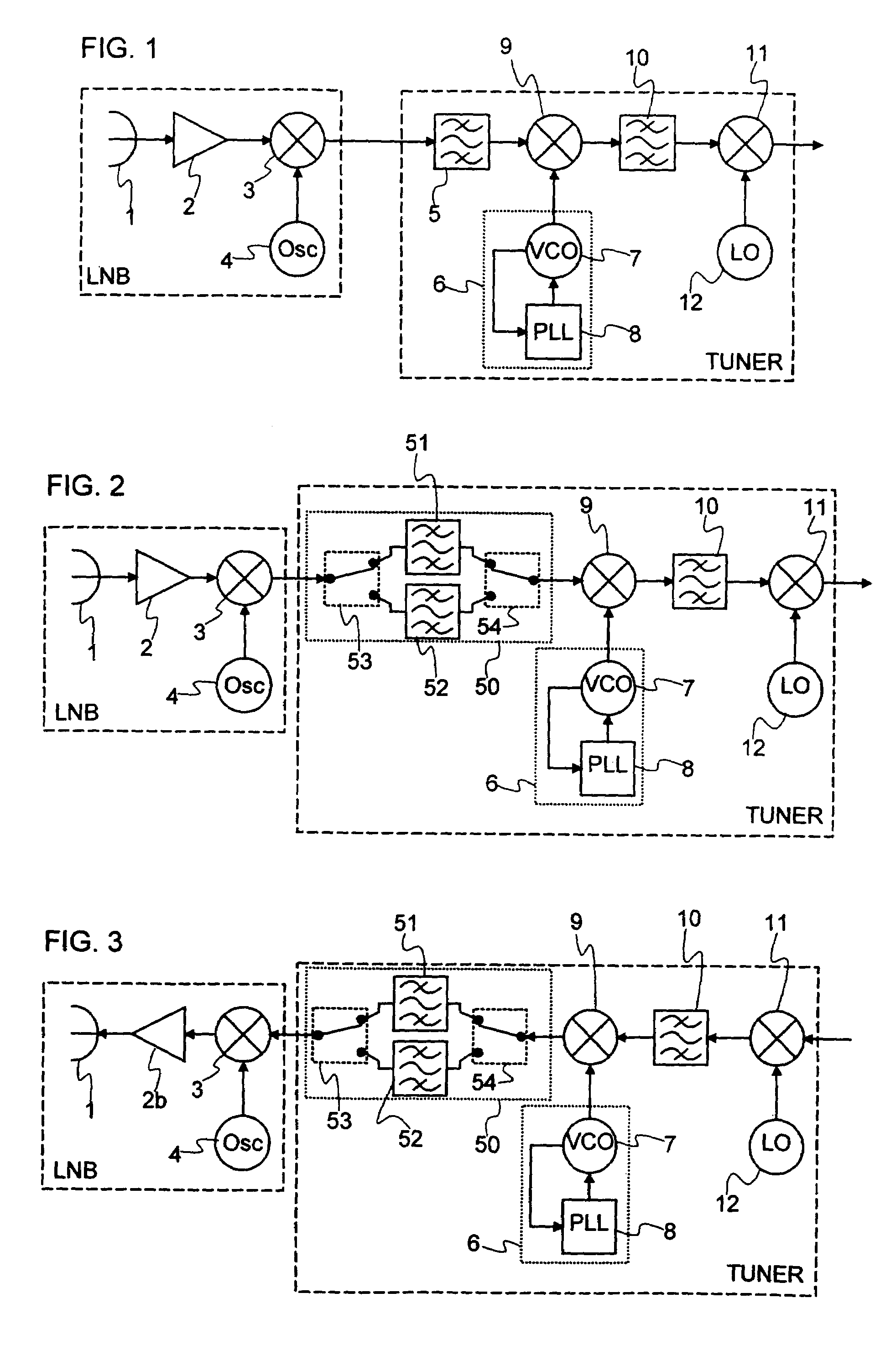
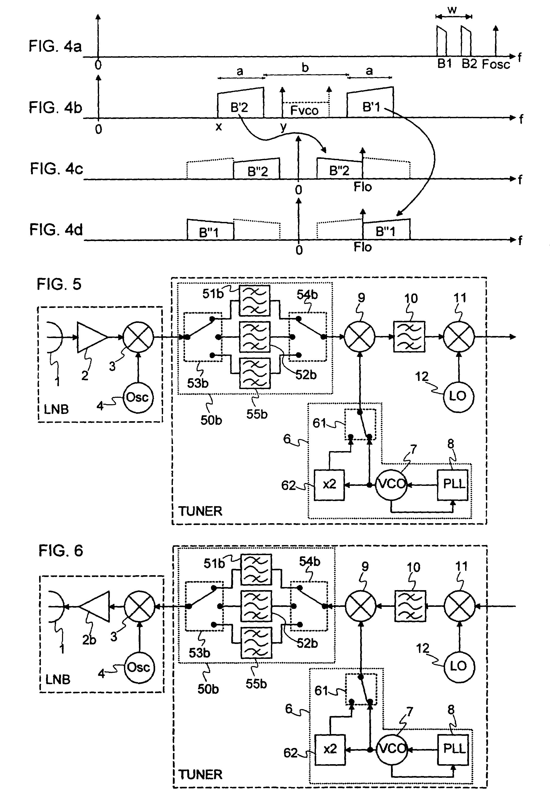
[0026]FIG. 2 shows a satellite receiver according to the invention. To make the operation of the receiver more clearly understood, reference should also be made to FIG. 4. This receiver operates within a high frequency range, for example the Ka band, and it has a bandwidth spread out over a spectral width w (FIG. 4a) with, for example, w equal to 1.9 GHz and lying between 18.3 and 20.2 GHz. The working part of the bandwidth is split into two sub-bands B1 and B2 (FIG. 4a) which have, for example, the same width, namely 500 MHz and are located between 18.3 and 18.8 GHz and between 19.7 and 20.2 GHz. The receiver comprises an LNB receiving block, mounted for example at the focus of a parabolic dish, and a TUNER internal unit.

[0027]The LNB block, of conventional structure, includes an antenna 1 followed by a low-noise amplifier 2. The signal delivered by the amplifier 2 is transposed to an intermediate frequency by means of a mixer 3 and an oscillator 4. The oscillator 4 delivers a sign...

second embodiment

[0044]An illustrative example of a transmitter according to the invention is shown in FIG. 6. This transmitter operates within the same frequency bands as the receiver of FIG. 5. The transmitter consists overall of the same components as the receiver, but is distinguished from the receiver by a reversal in the direction of the signal and the replacement of the amplifier 2 with a transmission amplifier 2b.

[0045]Many variants on the second embodiment are also possible, some of which are illustrated in FIG. 8. If the broader sub-band, for example B2, lies at a lower frequency than the narrower sub-band, for example B1, all that is required is to place the frequency of the oscillator 4 above the sub-band B1, as shown in FIG. 8a, in order to replace the narrower band on the lowest frequencies.

[0046]FIG. 8b illustrates a different distribution between the filters. The broadest part of the image of the broader sub-band is positioned at a lower frequency than the narrowest part. The circui...


PUM


Abstract

The invention provides a simple solution for a broadband transmitter/receiver for which the working bandwidth is split into at least two non-contiguous sub-bands. The invention uses a filtering means 50 which comprises at least two band-pass filters 51 and 52 provided with switching means 53 and 54. The use of two switched filters 51 and 52 makes it possible to use a single synthesizer 6 to scan two sub-bands of the working bandwidth. The frequency synthesizer 6 operates for one sub-band in supradyne mode and for the other sub-band in infradyne mode. In a variant, the invention uses a third filter and divides the bandwidth into three sub-bands.

Description

BACKGROUND OF THE INVENTION[0001]1. Field of the Invention[0002]The invention relates to a radiofrequency transmitter and / or receiver. More particularly, the invention relates to satellite broadcasting devices.[0003]2. Description of the Prior Art[0004]Satellite broadcasting has many advantages over radio transmission called “terrestrial” broadcasting. Among the advantages, mention may be made of the direct visibility between transmitter and receiver, the absence of echoes and, above all, a broad band of frequencies that can be used.[0005]The success of satellite broadcasting has had the effect of gradually saturating the spectrum of available frequencies. It is necessary to use ever higher frequencies with ever broader bandwidths. At the present time, a satellite broadcasts over several carriers lying within the same frequency band. As an example, a satellite television receiver may, for example, receive 20 channels lying between 11.7 GHz and 12.1 GHz.[0006]FIG. 1 shows an example ...

Claims


Application Information

Patent Timeline
IPC IPC(8): H04B1/18H04B1/40H03J5/24H04B1/04H04N5/38H04B1/16H04B1/26H04N5/44H04N7/20
CPCH03J5/244
Inventor HIRTZLIN, PATRICELE NAOUR, JEAN-YVESWURM, PATRICK
Owner INTERDIGITAL MADISON PATENT HLDG
Why Eureka
Try Eureka