Method for manufacturing a monolithic ink-jet printhead

a monolithic inkjet and printhead technology, applied in the direction of resistor details, resistors adapted for applying terminals, inking apparatus, etc., can solve the problems of complex manufacturing process, conflicting requirements, and complicated manufacturing process above printheads, so as to facilitate mass-production of printheads

Active Publication Date: 2007-10-02
HEWLETT PACKARD DEV CO LP
View PDF14 Cites 19 Cited by
  • Summary
  • Abstract
  • Description
  • Claims
  • Application Information

AI Technical Summary

Benefits of technology

[0017]It is preferable that a coating layer formed of diamond-like carbon (DLC) is formed on an external surface of the printhead. The DLC coating layer has high hydrophobic property and durability.
[0022]In a printhead according to the present invention, all of the above manufacturing and alignment requirements may be satisfied. Additionally, the elements of the printhead and a MOS integrated circuit are formed monolithically on the substrate, thereby achieving a more compact printhead.
[0029]In the method for manufacturing a monolithic ink-jet printhead according to the present invention, the elements of an ink-jet printhead and a MOS integrated circuit may be formed monolithically on a substrate, thereby facilitating mass-production of the printhead.

Problems solved by technology

The above requirements, however, tend to conflict with one another.
In order to manufacture a printhead having the above structure, the nozzle plate 11 and the substrate 10 should be separately manufactured and bonded to each other, resulting in a complicated manufacturing process and often causing misalignment when the nozzle plate 11 is bonded to the substrate 10.
As with the first conventional printhead manufacturing process, the above printhead manufacturing process is complicated, and misalignment may occur in the bonding process of the elements.

Method used


Image

  • Method for manufacturing a monolithic ink-jet printhead
  • Method for manufacturing a monolithic ink-jet printhead
  • Method for manufacturing a monolithic ink-jet printhead

Examples


first embodiment

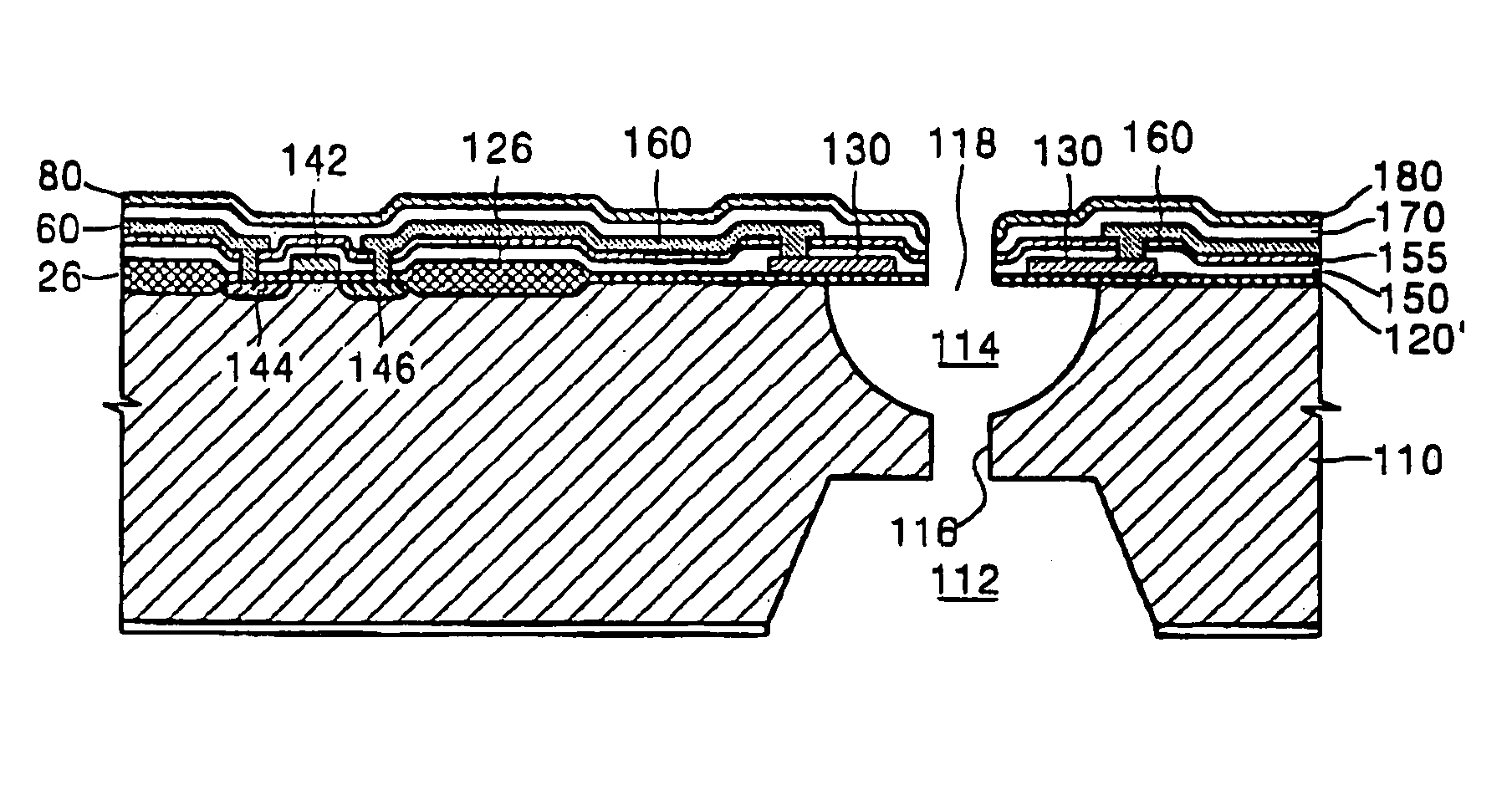
[0045]FIG. 4 illustrates a cross-sectional view of the vertical structure of an ink ejecting unit according to the present invention. As shown in FIG. 4, an ink chamber 114 filled with ink is formed on the surface of a substrate 110 of the ink ejecting unit, the ink supply manifold 112 for supplying ink to the ink chamber 114 is formed on a bottom surface of the substrate 110, and an ink channel 111 for connecting the ink chamber 114 to the ink supply manifold 112 is centrally formed in the bottom of the ink chamber 114. Preferably, the ink chamber 114 is formed in a nearly hemispheric shape. Preferably, the substrate 110 is formed of silicon, which is widely used in manufacturing integrated circuits. More preferably, the diameter of the ink channel 116 is smaller than that of a nozzle 118 to prevent the back flow of ink.

[0046]A silicon oxide layer 120′, in which the nozzle 118 is formed, is deposited on the surface of the substrate 110, thereby forming an upper wall of the ink cham...

second embodiment

[0094]FIGS. 20 through 23 illustrate cross-sectional views of stages in a manufacturing process of a printhead having an ink ejecting unit according to the present invention shown in FIG. 7.

[0095]The method for manufacturing a printhead having the ink ejecting unit shown in FIG. 7 is similar to the method for manufacturing a printhead having the ink ejecting unit shown in FIG. 4, except formation of the nozzle guide (210 of FIG. 7) is further included. That is, the method for manufacturing a printhead having the ink ejecting unit shown in FIG. 7 is initially the same as the stages shown in FIGS. 10-16. Subsequent steps are illustrated in FIGS. 20-23 and include the formation of the nozzle guide. Hereinafter, the method for manufacturing a printhead having the ink ejecting unit shown in FIG. 7 will be described to explain the above-described difference.

[0096]As shown in FIG. 20, after the stage shown in FIG. 16, the second passivation layer 170, the BPSG layer 155, the first passivat...


PUM

PropertyMeasurementUnit
thicknessaaaaaaaaaa
thicknessaaaaaaaaaa
thicknessaaaaaaaaaa

Abstract

A method for manufacturing the same, wherein the monolithic ink-jet printhead includes a manifold for supplying ink, an ink chamber having a hemispheric shape, and an ink channel formed monolithically on a substrate; a silicon oxide layer, in which a nozzle for ejecting ink is centrally formed in the ink chamber, is deposited on the substrate; a heater having a ring shape is formed on the silicon oxide layer to surround the nozzle; a MOS integrated circuit is mounted on the substrate to drive the heater and includes a MOSFET and electrodes connected to the heater. The silicon oxide layer, the heater, and the MOS integrated circuit are formed monolithically on the substrate. Additionally, a DLC coating layer having a high hydrophobic property and high durability is formed on an external surface of the printhead.

Description

CROSS REFERENCE TO RELATED APPLICATION[0001]This is a divisional application based on U.S. application Ser. No. 10 / 278,991, filed on Oct. 24, 2002, now U.S. Pat. No. 6,692,112, the entire contents of which is hereby incorporated by reference.BACKGROUND OF THE INVENTION[0002]1. Field of the Invention[0003]The present invention relates to an ink-jet printhead. More particularly, the present invention relates to a monolithic ink-jet printhead having a hemispheric ink chamber and working in a bubble-jet mode, and a method for manufacturing the same.[0004]2. Description of the Related Art[0005]In general, ink-jet printheads eject small ink droplets for printing at a desired position on a paper and print out images having predetermined colors. Ink ejection methods for ink-jet printers include an electro-thermal transducer method (bubble-jet type) for ejecting an ink droplet by generating bubbles in ink using a heat source, and an electro-mechanical transducer method for ejecting an ink dr...

Claims


Application Information

Patent Timeline
Patent Type & Authority Patents(United States)
IPC IPC(8): H05B3/00B41J2/175B41J2/14B41J2/16
CPCB41J2/14137B41J2/1601B41J2/1628B41J2/1629B41J2/1631B41J2/1642B41J2/1646Y10T29/49094B41J2002/1437B41J2202/13Y10T29/49098Y10T29/49101Y10T29/49401Y10T29/49083B41J2/175
Inventor KIM, HYEON-CHEOLOH, YONG-SOOKUK, KEONYOON, KWANG-JOONMIN, JAE-SIKLEE, SANG-HYUNLEE, CHANG-SEUNGBAEK, SEOG SOONLEE, SANG-WOOKSHIN, JONG-CHEOL
Owner HEWLETT PACKARD DEV CO LP
Why Eureka
Try Eureka