
Volumetric densiometer flask

a densiometer and volumetric technology, applied in the field of volumetric densiometer laboratory flasks, can solve the problems of inaccurate density determination and inability to accurately measure density, and achieve the effects of improving resolution, more precise, and predictable laboratory results

Inactive Publication Date: 2007-10-02
WALKER STEPHAN HOWARD
View PDF20 Cites 7 Cited by
  • Summary
  • Abstract
  • Description
  • Claims
  • Application Information

AI Technical Summary

Benefits of technology

"The present invention is a volumetric laboratory flask for determining the density of a chemical that has been solubilized in solution. The flask has a unique design that allows for more accurate and reliable results compared to conventional methods. It is also fast, safe, and easy to use. The procedure for determining the density involves measuring the sample, adding a solvent, shaking the flask, and measuring the resulting solution. The results are statistically analyzed. Overall, the invention improves the accuracy and precision of laboratory results."

Problems solved by technology

However, such methods are not as accurate as they could be, and sometimes result in inaccurate density determinations.

Method used


Image

  • Volumetric densiometer flask
  • Volumetric densiometer flask
  • Volumetric densiometer flask

Examples


example i

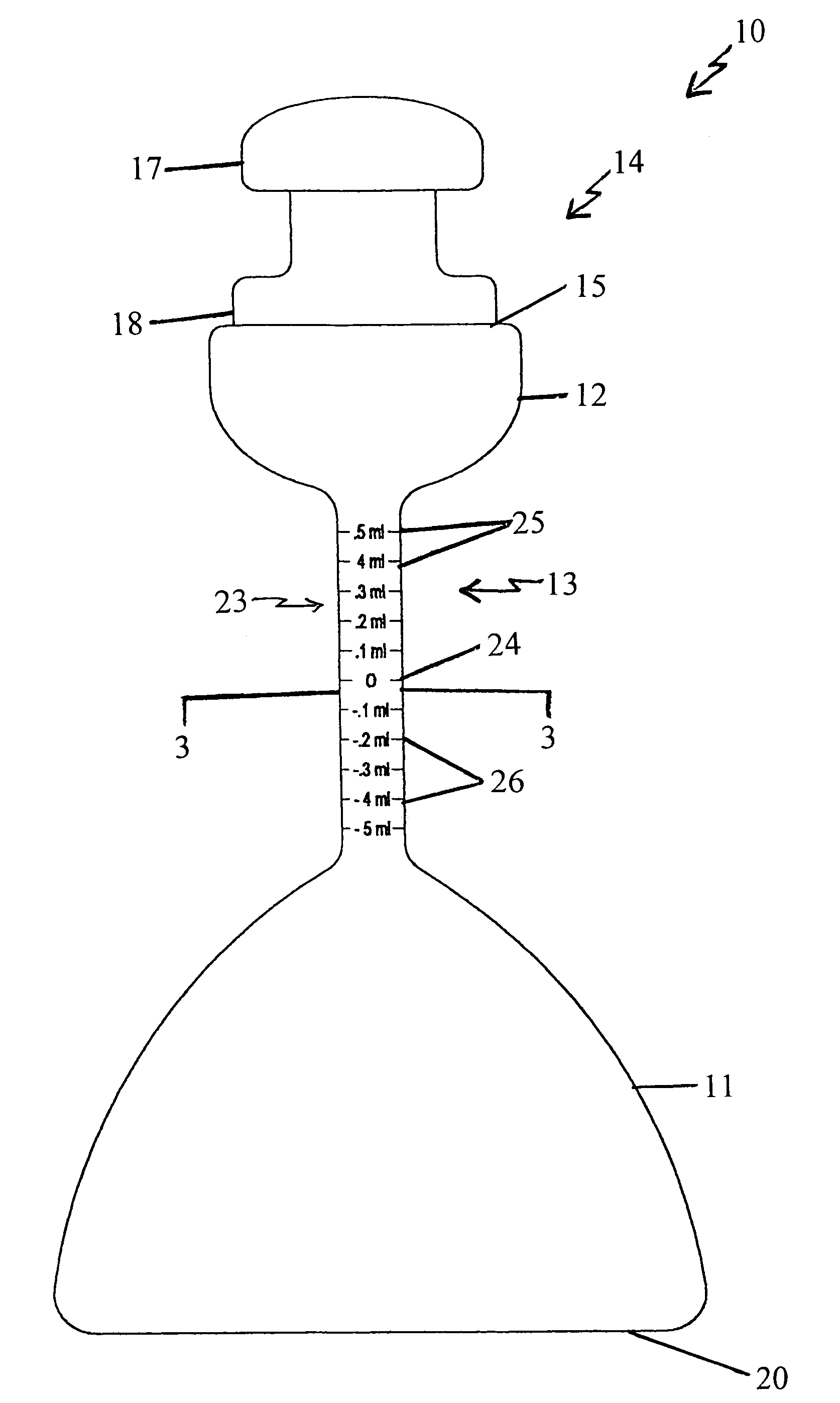
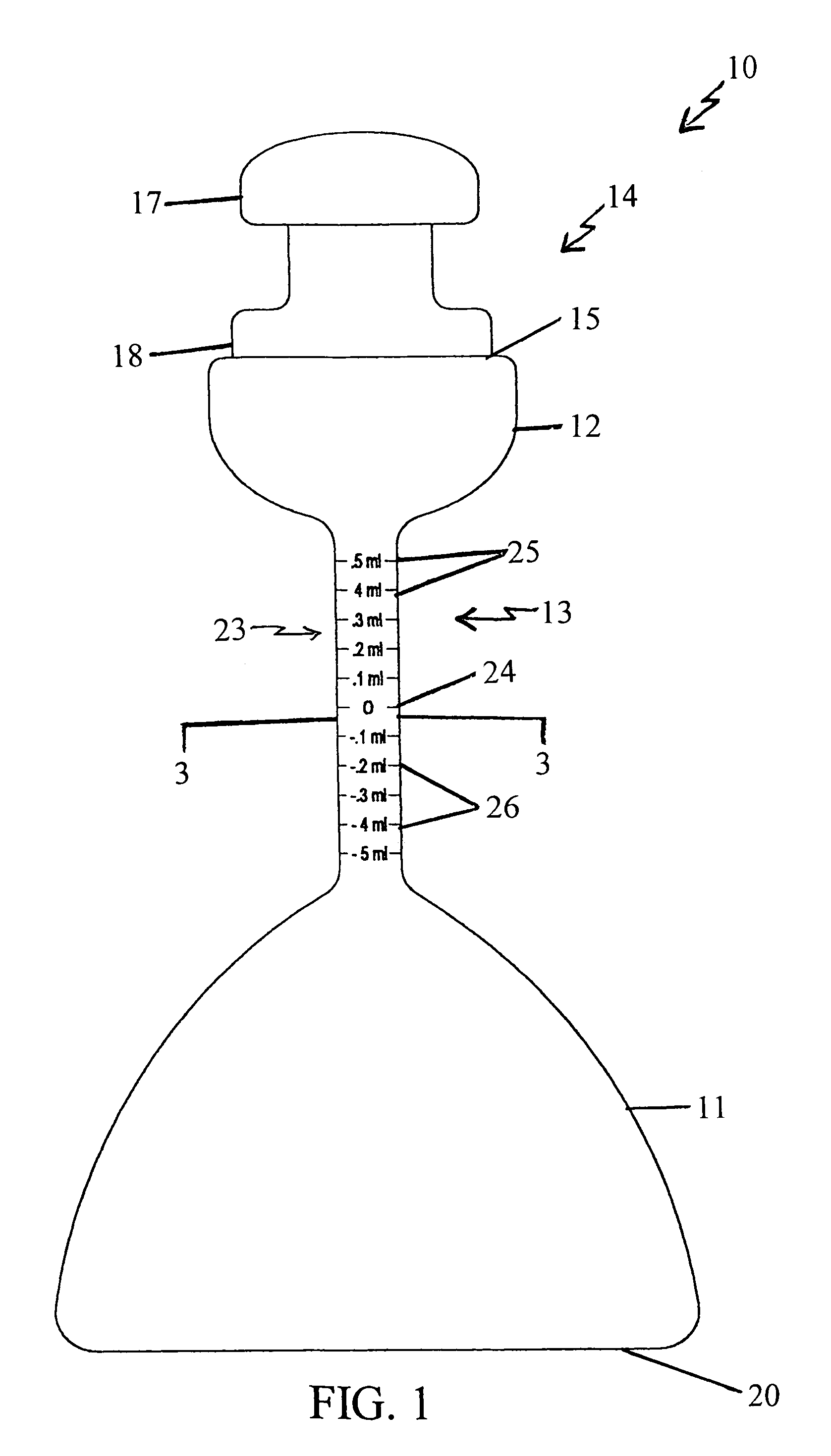
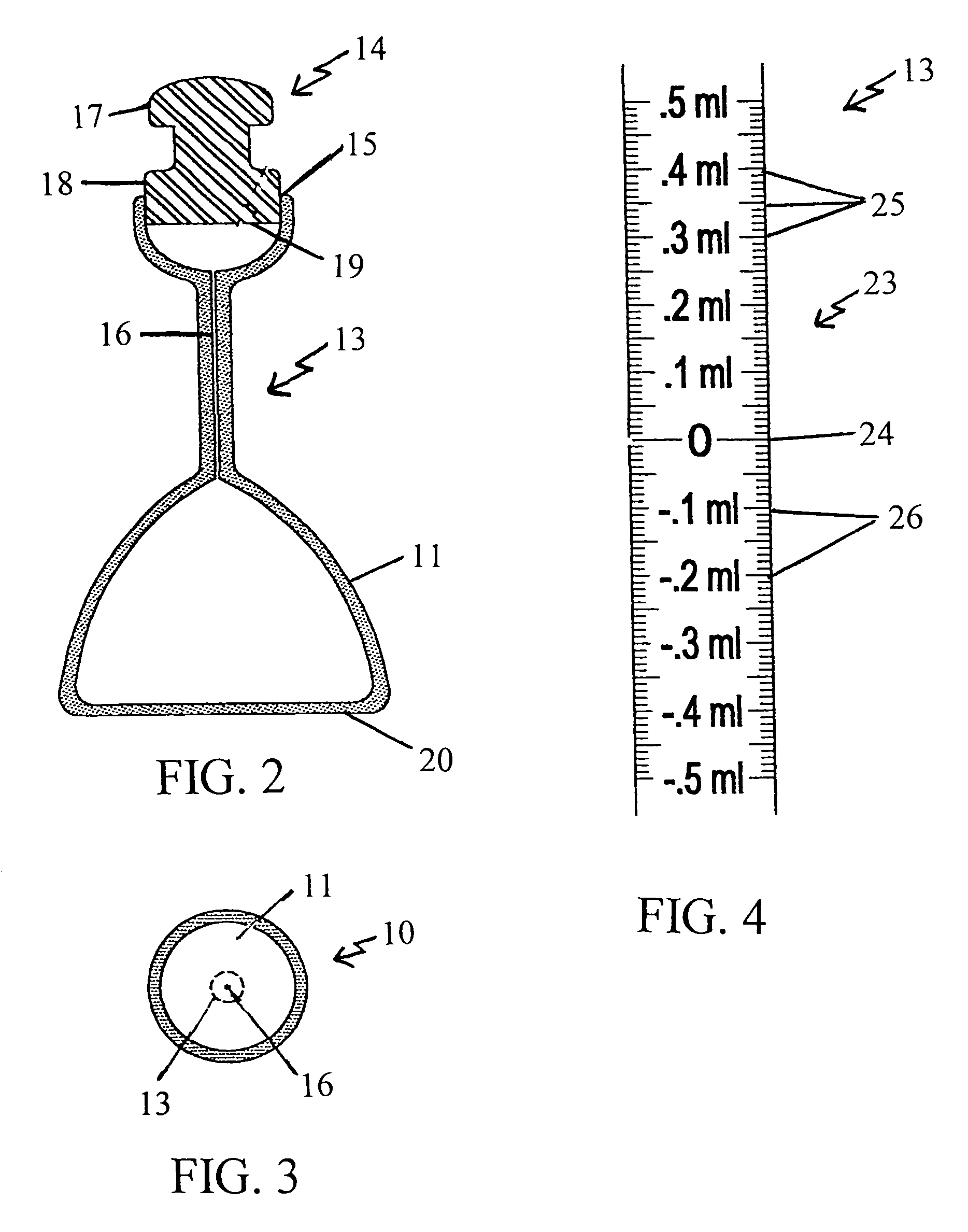
[0077]Exemplifying the procedure described hereinabove, 100 ml. of deionized water is poured into the mouth of a volumetric densiometer flask according to the present invention at standard temperature and pressure. The solvent (water) is shaken down to the first bulbous portion, and the meniscus of the solvent is brought up to the zero marking on the neck of the flask using a small amount of the solvent in a dropper. The stopper is then inserted in the mouth and the flask is inverted to return the solvent to the second bulbous portion. (The second bulbous portion accommodates 25 milliliters of solvent.) The flask is placed on a table, the stopper is removed, and a 0.002 gram sample of reagent grade potassium chloride is poured into the mouth of the same flask. The stopper is inserted and the flask is shaken by hand. The flask with this solution is placed in a standard temperature (78 degrees Fahrenheit or 20 degrees Celsius) water bath and allowed to settle for about fifteen minutes...

example ii

[0089]A 50 ml. mixture of concentrated 70% nitric acid and 30% hydrochloric acid (Aqua Regia) is poured into the mouth of a volumetric densiometer flask according to the present invention at standard temperature and pressure. The solvent (the acids) is shaken down to the first bulbous portion, and the meniscus of the solvent is brought up to the zero marking on the neck of the flask using a small amount of the solvent in a dropper. The stopper is inserted in the mouth of the flask, and the flask is inverted to return the solvent to the second bulbous portion. The second bulbous portion of this flask accommodates 25 milliliters of liquid. The bottom of the flask is then placed on a table, the stopper is removed, and a 1.0 milligram sample of elemental iron is poured into the mouth of the same flask. The stopper is again inserted and the flask is shaken by hand. The flask with this solution is placed in a standard temperature (78 degrees Fahrenheit or 20 degrees Celsius) water bath, a...


PUM

PropertyMeasurementUnit
diameteraaaaaaaaaa
diameteraaaaaaaaaa
lengthaaaaaaaaaa

Abstract

A volumetric densiometer flask for determining the volumetric density of a solute includes:(a) a first bulbous portion in a lower end section of the flask;(b) a second bulbous portion in an upper end section of the flask, the second bulbous portion comprising an open mouth at its upper end;(c) a central neck comprising a central channel in open communication with the first bulbous portion at an upper end of the neck, and the second bulbous portion at an opposite, lower end of the neck; and(d) a removable stopper that is closely insertable into the mouth of the second bulbous portion, the mouth being correspondingly sized to a lower end of the stopper. Also included herein is a procedure for determining the volumetric density of a given sample using the volumetric densiometer flask.

Description

CROSS REFERENCE TO RELATED DOCUMENT[0001]This invention was described in Disclosure Document Number 539823, which was received by the U.S. Patent & Trademark Office on Oct. 9, 2003.BACKGROUND OF THE INVENTION[0002]1. Technical Field[0003]The present invention relates to a volumetric densiometer laboratory flask for determining the volumetric density of a chemical in solution.[0004]1. Background Information[0005]Conventional laboratory methods are available for determining the volumetric density of a particular chemical in solution for use in concentration calculations. However, such methods are not as accurate as they could be, and sometimes result in inaccurate density determinations.[0006]It has been found herein that since solutions expand or contract depending on the characteristics of the particular solution, a volumetric densiometer flask that allows such reactions to take place and facilitates measurements after the reaction would be quite useful. The volumetric densiometer f...

Claims


Application Information

Patent Timeline
Patent Type & Authority Patents(United States)
IPC IPC(8): G01N9/00G01F19/00
CPCG01N9/04
Inventor WALKER, STEPHAN HOWARD
Owner WALKER STEPHAN HOWARD
Learn More