System and method for boosted direct injection engine

a direct injection engine and system technology, applied in the direction of machines/engines, electric control, combustion engines, etc., can solve the problems of reducing fuel efficiency, and achieve the effects of reducing residuals, increasing engine power density, and reducing fuel efficiency

Active Publication Date: 2007-10-02
FORD GLOBAL TECH LLC
View PDF8 Cites 71 Cited by
  • Summary
  • Abstract
  • Description
  • Claims
  • Application Information

AI Technical Summary

Benefits of technology

[0001]Engines may use boosting devices, such as turbochargers, to increase engine power density. However, engine knock may occur due to increased combustion temperature, thus requiring spark retard, which in turn reduced fuel efficiency.
[0002]The inventors herein have recognized that under some conditions, utilizing intake manifold pressure boosting in which valve overlap near top dead center (TDC) is present may be advantageous in reducing residuals. Further, such valve timing and pressure boosting, in combination with direct injection fueling (e.g., in-cylinder injection) may be used to reduce charge temperatures and reduce the tendency for auto ignition (knock), thus enabling improved torque output and fuel economy under selected conditions.
[0003]However, the inve...

Problems solved by technology

However, engine knock may occur due to increased combustion tempera...

Method used


Image

  • System and method for boosted direct injection engine
  • System and method for boosted direct injection engine
  • System and method for boosted direct injection engine

Examples


Embodiment Construction

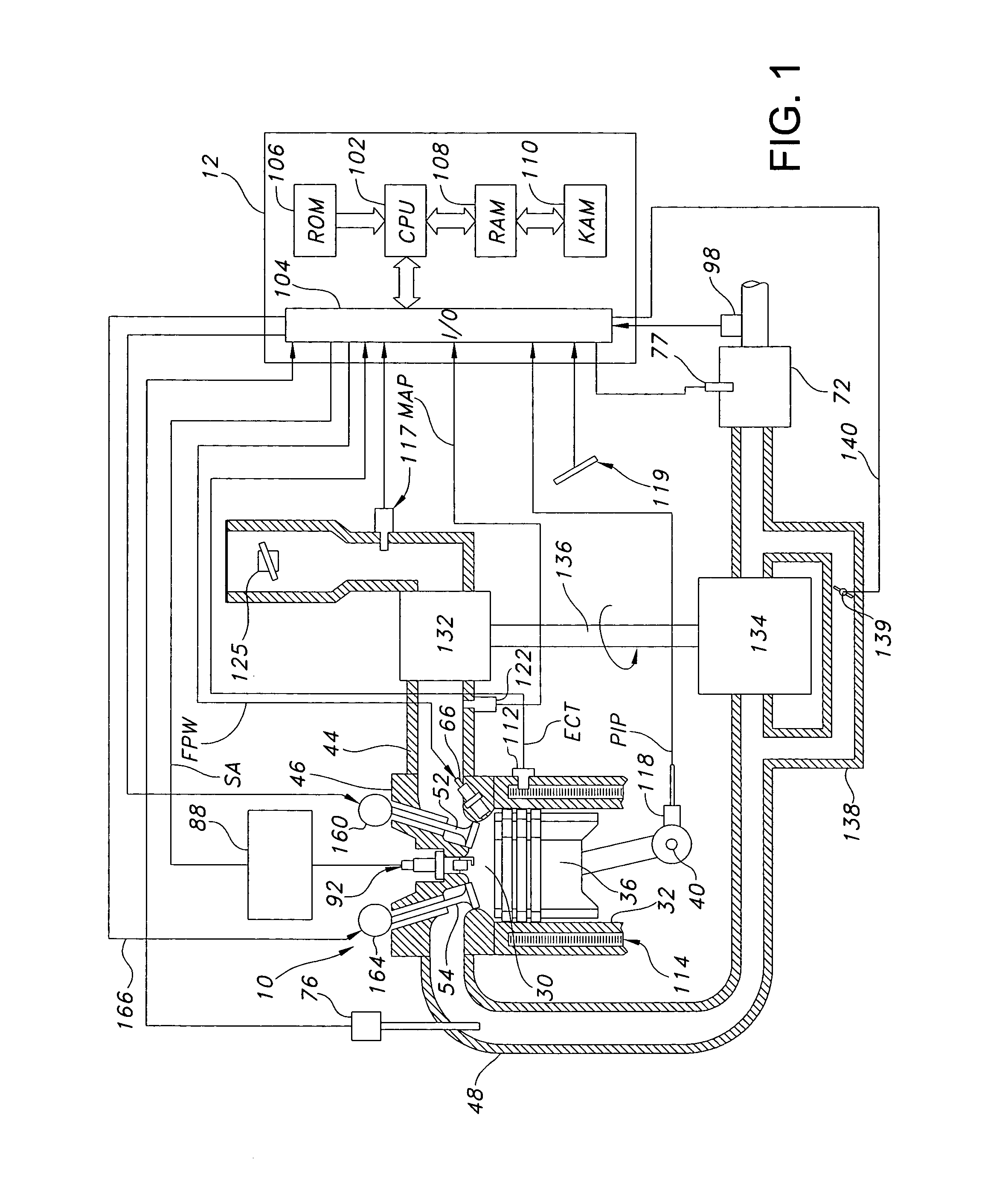
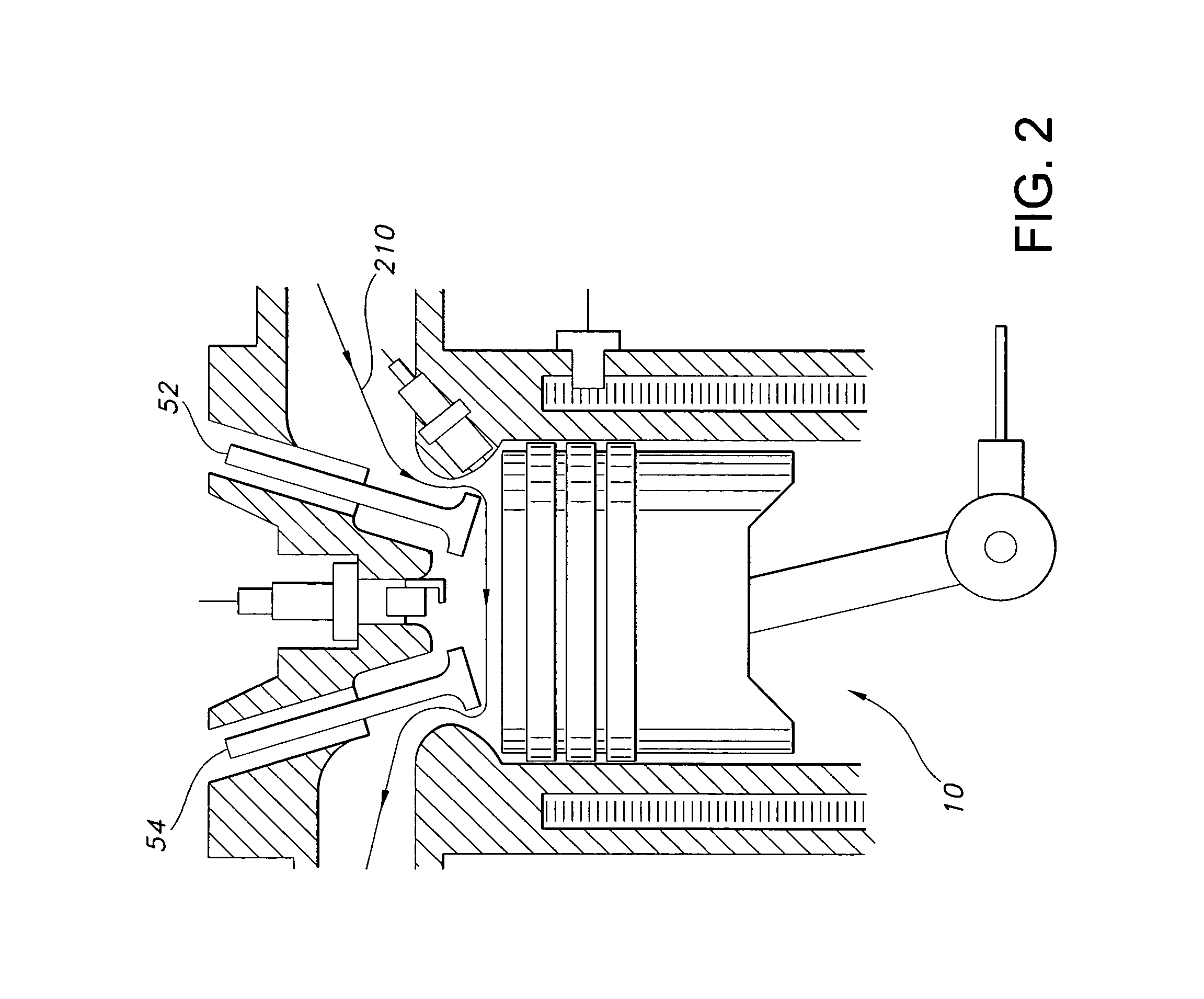
[0008]Referring now to FIG. 1, internal combustion engine 10, comprising a plurality of cylinders, one cylinder of which is shown in FIG. 1, is controlled by electronic engine controller 12. Engine 10 includes cylinder head 46, combustion chamber 30 and cylinder walls 32 with piston 36 positioned therein and connected to crankshaft 40. Combustion chamber 30 is shown communicating with intake manifold 44 and exhaust manifold 48 via respective intake valve 52 and exhaust valve 54. In this example, a single intake valve and exhaust valve are shown; however, there may be multiple intake valves and / or multiple exhaust valves. Each intake and exhaust valve may be operated by a camshaft, or both may be operated by a common camshaft. Variable valve timing operation may be used via a hydraulic actuator. In an alternative embodiment, the valves may be operated by an electromechanically controlled valve coil and armature assembly. In the example of FIG. 1, an intake cam 160 is shown for actuat...


PUM


Abstract

A method for operating and engine having a cylinder with at least an intake and exhaust valve, comprising of performing a combustion cycle in the cylinder in which exhaust valve closing occurs after intake valve opening thereby creating valve overlap, boosting intake air above exhaust pressure, where said boosted intake air is inducted into said cylinder while said intake valve is open and at least a first portion of said inducted boosted intake air flows past the exhaust valve with both said intake and exhaust valves are open during said overlap, directly injecting fuel to said cylinder that is combusted in said cylinder, where a beginning of said fuel injection occurs after said exhaust valve closing and said directly injected fuel is mixed with at least a second portion of said inducted boosted intake air, and combusting said mixture at a rich air-fuel ratio.

Description

BACKGROUND AND SUMMARY[0001]Engines may use boosting devices, such as turbochargers, to increase engine power density. However, engine knock may occur due to increased combustion temperature, thus requiring spark retard, which in turn reduced fuel efficiency.[0002]The inventors herein have recognized that under some conditions, utilizing intake manifold pressure boosting in which valve overlap near top dead center (TDC) is present may be advantageous in reducing residuals. Further, such valve timing and pressure boosting, in combination with direct injection fueling (e.g., in-cylinder injection) may be used to reduce charge temperatures and reduce the tendency for auto ignition (knock), thus enabling improved torque output and fuel economy under selected conditions.[0003]However, the inventors have also recognized that under some conditions during valve overlap in which both intake and exhaust valves are concurrently at least partially open near TDC (such as near the end of the exha...

Claims


Application Information

Patent Timeline
IPC IPC(8): F02B25/00F02B29/06
CPCF02D13/0261F02D41/0007F02D41/405F02D41/0032F02B25/145F02B23/104Y02T10/18F02B37/00F02B2075/125F02D13/0215F02D13/0249F02D2041/001F02D2041/389Y02T10/44Y02T10/123Y02T10/144Y02T10/12Y02T10/40
Inventor CUNNINGHAM, RALPH WAYNEHOARE, GRAHAMSHELBY, MICHAEL HOWARDSURNILLA, GOPICHANDRA
Owner FORD GLOBAL TECH LLC
Why Eureka
Try Eureka